


Installation Safety Information 34 Installation and Specifications
329
Installation Safety Information
WARNING If multiple instruments are connected to a patient, the sum of the leakage currents may exceed the
limits given in IEC/EN60601-1. Consult your service personnel.
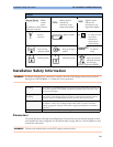
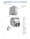
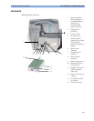
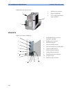
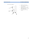
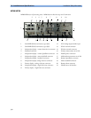
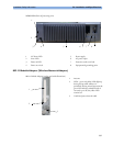
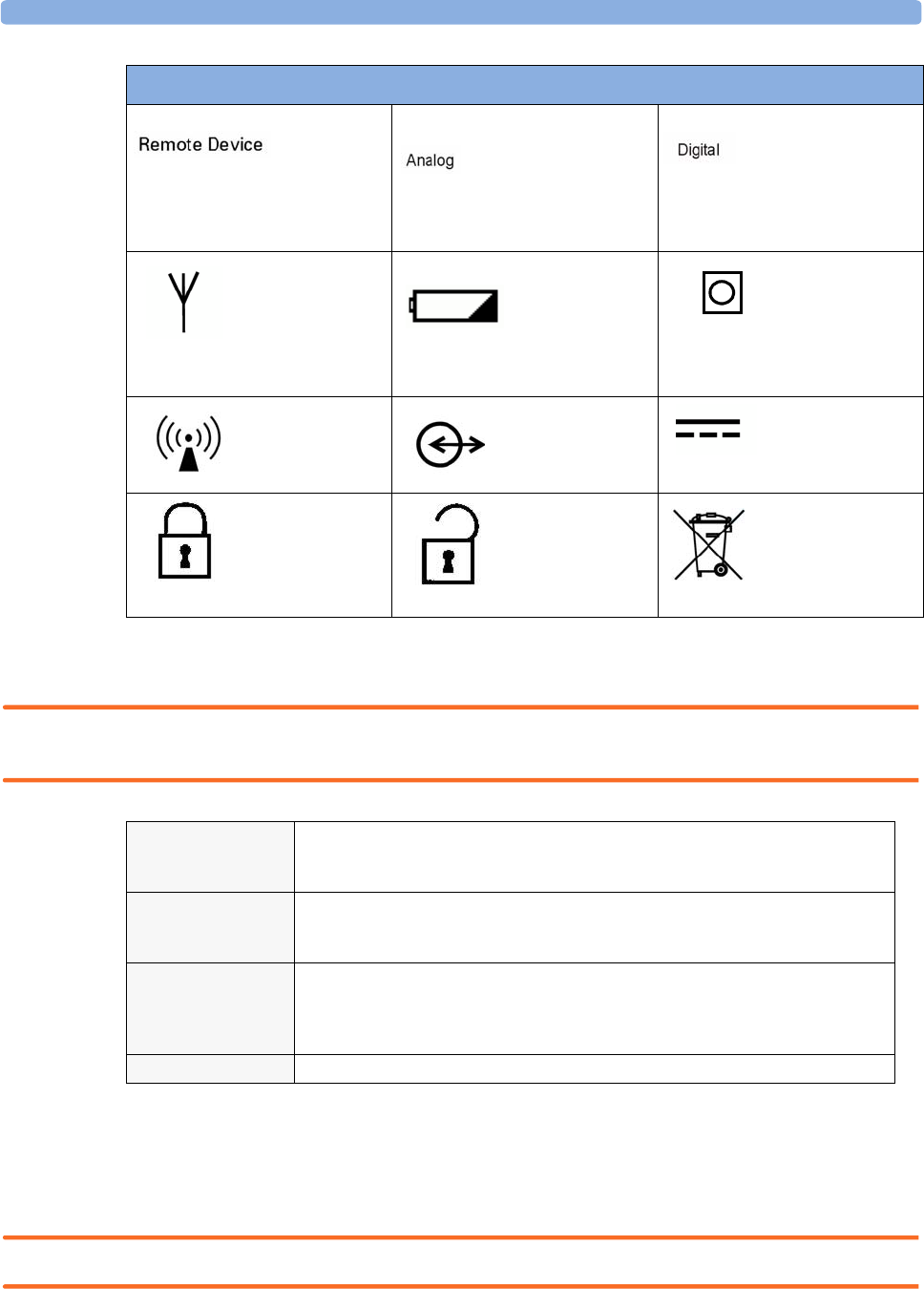
Connectors
The actual placement of boards and configuration of connections for your monitor depends on how
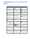
your hardware has been configured. See the symbols table on page 328 to see which symbols are used
to mark the connections.
WARNING Connect only medical devices to the ECG output connector socket.
Philips
remote
device
(SpeedPoint or Alarm Device)
connection indicator
Analog interface
indicator for
connection to any
analog video display
Digital interface
indicator for
connection to any
digital video display
Antenna
connector
Battery symbol 12 Volt DC LAN
connection
indicator for
connection to
serial interface
Non-ionizing
radiation symbol
Data input/output
symbol
12 Volt DC
socket
Locked position Unlocked position
Always use separate
collection for waste
electrical and
electronic equipment (WEEE)
Symbols
LAN/SER
12V
12V
Grounding The monitors or the MP80/MP90 processing unit must be grounded during operation. If
a three-wire receptacle is not available, consult the hospital electrician. Never use a three-
wire to two-wire adapter.
Equipotential
Grounding
If the monitors or MP80/MP90 processing unit are used in internal examinations on the
heart or brain, ensure that the room incorporates an equipotential grounding system to
which the monitor and MP80/MP90 processing unit have separate connections.
Combining equipment Combinations of medical equipment with non-medical equipment must comply with
IEC 60601-1-1. Never use a multiple portable socket-outlet or extension cord when
combining equipment unless the socket outlet is supplied specifically for use with that
equipment.
Fusing The monitors use double pole/neutral fusing.