


4 - 14
4. SYSTEM STARTUP
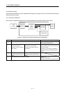
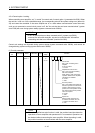
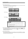
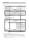
(1) When selecting the driver input
When 1 (driver input) is selected as the sensor destination, the sensor (LSP, LSN, DOG) status connected
to the driver (such as a servo amplifier) is imported via SSCNET.
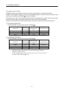
(a) MR-J4(W
)- B is used as a servo amplifier
1) MR-J4-
B
Signal
Name
Destination connector
pin No.
Abbreviation
LSP CN3-2 D11
LSN CN3-12 D12
DOG CN3-19 D13
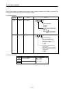
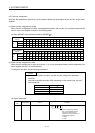
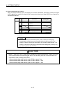
2) MR-J4W2-
B
Signal
Name
Destination
connector pin No.
Abbreviation
(
: A, B)
A-axis B-axis
LSP CN3-7 CN3-20 DI1
LSN CN3-8 CN3-21 DI2
DOG CN3-9 CN3-22 DI3
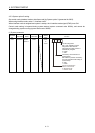
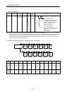
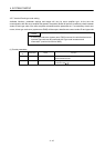
3) MR-J4W3-
B
Signal
Name
Destination connector pin No.
Abbreviation
(
: A, B, C)
A-axis B-axis C-axis
LSP CN3-7 CN3-20 CN3-1 DI1
LSN CN3-8 CN3-21 CN3-2 DI2
DOG CN3-9 CN3-22 CN3-15 DI3
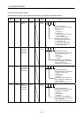
POINT
• For sensor connection to the driver, refer to the instruction manual of the
driver.
• If communication error (system error E401 to E407) occurs, sensor (LSP,
LSN, DOG) input status turns off.
• If communication error (system error E400) occurs, the input status of the
corresponding axis turns off.
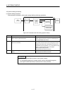
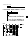
(2) When selecting the digital input
When 2 (digital input) is selected as the sensor destination, the digital input signal (DI_
) is used as
the sensor (LSP, LSN, DOG). Specify the digital input signal (DI_
) in the sensor signal connection
specification (parameter No.021A to 021C).
Refer to Section 6.26 and 6.27.
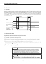
(3) When selecting not connected
When 3 (not connected) is selected as the sensor destination, the sensor (LSP/LSN/DOG) is not detected.
Limit switch functions are always invalid. In the home position return using the proximity dog, the position
board operates without detected proximity dog.