


10 - 33
10. TABLE MAP
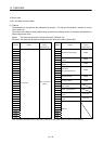
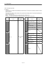
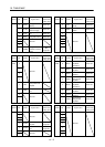
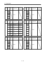
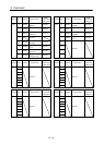
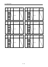
10.6.2 Axis data status table
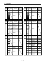
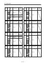
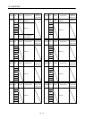
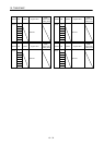
(1) Table list
The addresses in the table are the addresses for the first axis. For the axis 2 and above, increase in units of
C0h for each axis.
The column in the table for when tandem drive (synchronous) is being used is for axis data classification for
when using tandem drive.
Master : The data only valid for the master axis (refer to Section 8.3)
Each axis: The data valid for both the master axis and slave axis (refer to Section 8.3)
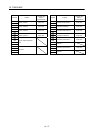
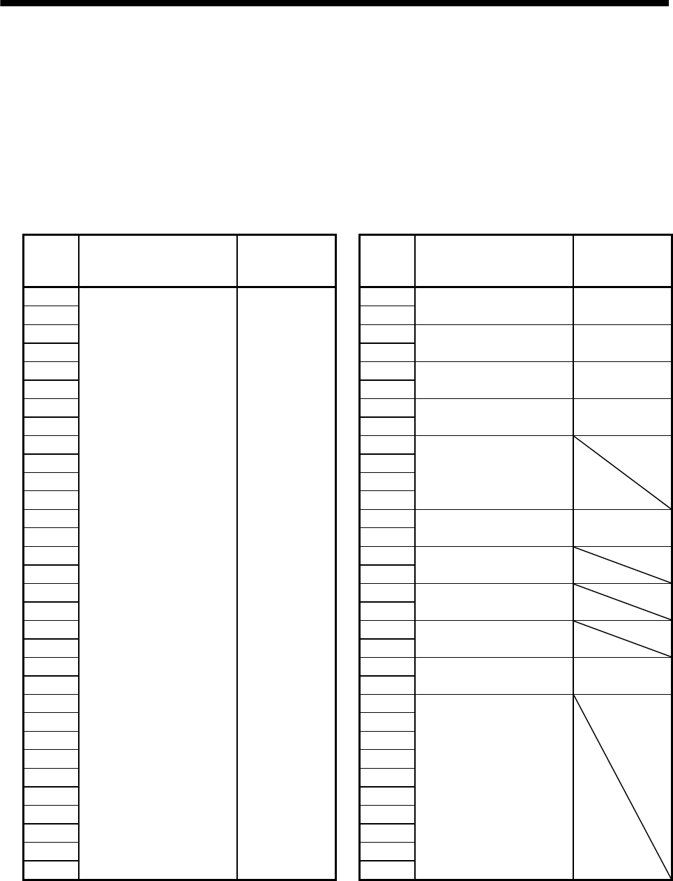
Address Content
When in parallel
drive
(synchronous)
Address Content
When in parallel
drive
(synchronous)
1060
Status bit
Refer to (2) of this
section
1080
Operation alarm number Master
1061 1081
1062 1082
Specific operation alarm
number
Master
1063 1083
1064 1084
Servo alarm number Each axis
1065 1085
1066 1086
Specific servo alarm number Each axis
1067 1087
1068 1088
Reserved
1069 1089
106A 108A
106B 108B
106C 108C
Operation point number Master
106D 108D
106E 108E
Maximum position command
buffer number
106F 108F
1070 1090
Transmit position command
buffer number
1071 1091
1072 1092
Control mode status
1073 1093
1074 1094
Executing pass position
condition number
Master
1075 1095
1076 1096
Reserved
1077 1097
1078 1098
1079 1099
107A 109A
107B 109B
107C 109C
107D 109D
107E 109E
107F 109F