


1 - 16
1. SUMMARY
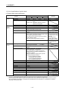
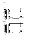
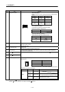
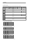
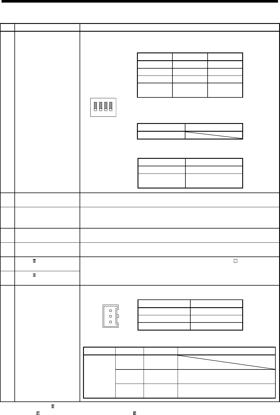
No. Item Function
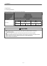
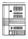
1) Setting switch (SW1)
ON
1234
<Board ID selection>
Define a board ID in order to distinguish between multiple position
boards.
Switch 2 Switch 1 Board ID
ON ON 3
ON OFF 2
OFF ON 1
OFF OFF
0
(default value)
<For manufacturer setting>
This switch is provided for manufacturer setting.
Make sure the switch is always OFF.
Switch 3 For manufacturer setting
OFF
<Interrupt output mask selection>
Masks interrupt output when interrupt occurs.
Switch 4 Interrupt output mask
ON Valid
OFF
Invalid
(default value)
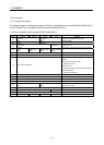
2) PCI Express
®
link (green) PCI Express
®
link up: ON
PCI Express
®
disconnected: OFF
3) Operation indicator (green) At power ON: ON
At system startup: Flicker
At power OFF: OFF
4) Error indicator (red) Normal: OFF
At system error (E001 to E302) occurrence: ON
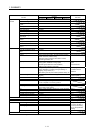
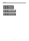
5) USB connector A communication connector to connect with the position board test tool, MR Configurator2.
(connects MR-J3USBCBL3M)
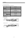
6) SSCNET connector (line 1)
(Note 1)
Connector for communication with a servo amplifier. (connects MR-J3BUS M)
7) SSCNET connector (line 2)
(Note 1)
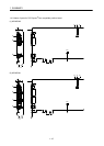
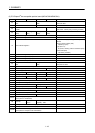
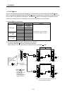
8) Forced stop input connector The following is the pin layout and connections of the forced stop input connector as viewed
from the front.
1
2
3
Pin No. Signal name
1 EMI
2 No connect
3 EMI.COM
Note. Do not connect to any of the terminals explained as "No connect".
<Cable-side connector model name>
Manufacturer Name Model Reference
Molex
Crimp
housing
51103-0300
Crimp
terminal
50351-8100
Applicable wire size (AWG): 22, 24, 26, 28
Two crimp terminals are required per housing.
Hand crimp
tool
63811-8100 Applicable terminal: 50351
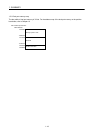
Note 1. Put the SSCNET cable in the duct or fix the cable at the closest part to the position board with bundle material in order to prevent
SSCNET
cable from putting it's own weight on SSCNET connector.