


1 - 11
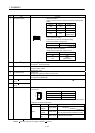
1. SUMMARY
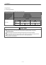
Function
Contents
Remarks
MR-MC210 MR-MC211 MR-MC240 MR-MC241
Application
function
Gain switching Provided
PI-PID switching Provided
Absolute position detection
system
Provided
Home position return request Provided
Other axes start Provided
High response I/F Provided
In-position signal Provided
Digital input/output Provided
Servo amplifier general
input/output
Provided
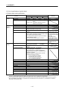
Dual port memory exclusive
control
Provided
Pass position interrupt Provided
Mark detection Provided
Continuous operation to torque
control
Provided
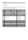
Help function Reading/writing parameters Provided
Changing parameters at the
servo
Provided
Alarm and system error Provided
Monitor Current command position, Current feedback position,
Speed command, Position droop,
Electrical current command, Servo alarm number,
External signal status, etc.
Can be latched
High speed monitor Current command position, Current feedback position,
Moving speed, Feedback moving speed,
External signal, Electrical current feedback,
Position droop (interface mode only)
Updated per control
cycle
Can be latched
Interrupt
During start operation, Operation stoppage
(During operation, in-position, during smoothing of
stopping, rough match, etc.)
When alarm goes off (servo alarm/operation alarm), etc.
Interrupt generation
conditions can be
selected.
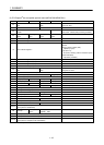
User watchdog function Provided (Check for the watchdog of the of the user
program)
Processed by
software.(Note 3)
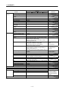
Software reboot function Provided
Parameter backup Parameters can be saved to the flash ROM.
Test mode By connecting MR Configurator2 via the position board,
the servo amplifier can be simply tested.
Reconnect/disconnect function Provided
Sampling
The maximum sampling point: 65536.
(Ring buffer of 8192 points)
Log History of start operation, alarms, etc, can be recorded.
Operation cycle monitor function Provided
External forced stop disabled Provided
Amplifier-less axis function Provided
Alarm history function Alarm history is saved to the flash ROM.
Tandem drive Up to 2 axes × 8 groups
Interface mode Positioning control, speed-torque control
Board ID 0 to 3 Select using DIP-SW
DI Limit switch None DI signals are input from
the servo amplifier or
the dual port memory,
etc. by the parameter
setting.
Limit switch None
Proximity dog None
Forced stop 1 point
DO None
Note 3. This is not the watch dog for the CPU on the position board.