


10 - 49
10. TABLE MAP
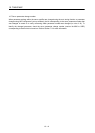
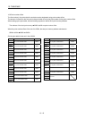
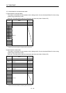
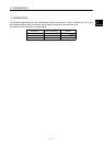
10.11 Mark detection command/status table
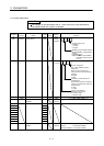
(1) Mark detection command table
The column in the table for when tandem drive is being used is for axis data classification for when using
tandem drive synchronous mode.
Each axis: The data valid for both the master axis and slave axis (refer to Section 8.3)
Address Name
When in
tandem drive
B4F0 Read complete buffer number 1 Each axis
B4F1 Read complete buffer number 2 Each axis
B4F2
Reserved
B4F3
B4F4
B4F5
B4F6
B4F7
B4F8
B4F9
B4FA
B4FB
B4FC
B4FD
B4FE
B4FF
Note. The addresses above are the addresses for the first axis.
For the second axis and after, increase by 20h for each axis.
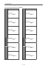
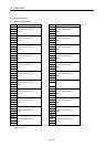
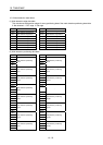
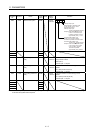
(2) Mark detection status table
The column in the table for when tandem drive is being used is for axis data classification for when using
tandem drive synchronous mode.
Each axis: The data valid for both the master axis and slave axis (refer to Section 8.3)
Address Name
When in
tandem drive
B500 Start data storage area 1 Each axis
B501
Number of continuous latch data
storages 1
Each axis
B502 Number of mark detections counter 1 Each axis
B503 Mark detection mode 1 Each axis
B504 Start data storage area 2 Each axis
B505
Number of continuous latch data
storages 2
Each axis
B506 Number of mark detections counter 2 Each axis
B507 Mark detection mode 2 Each axis
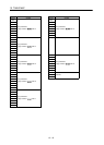
B508
Reserved
B509
B50A
B50B
B50C
B50D
B50E
B50F
Note. The addresses above are the addresses for the first axis.
For the second axis and after, increase by 20h for each axis.