


6 - 116
6. APPLICATION FUNCTIONS
6.30.3 Function details
(1) Combinations with sensor input method
By setting the sensor input method to driver input, and setting the mark detection signal numbers (DI1 to
DI3), sensors (LSP/LSN/DOG) can be used in combination with the mark detection function.
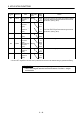
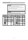
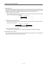
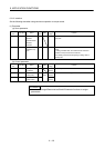
Example 1: When sensor input method is set to driver input and mark detection signal number specification
1 is set to DI3
Name Signal allocation
DI1 LSP
DI2 LSN
DI3 DOG(mark detection 1)
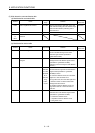
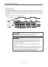
Example 2: When sensor input method is set to a setting other than driver input and mark detection signal
number specification 2 is set to DI1
Name Signal allocation
DI1
General input 1
(mark detection 2)
DI2 General input 2
DI3 General input 2
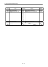
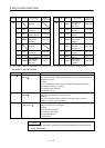
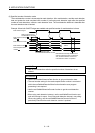
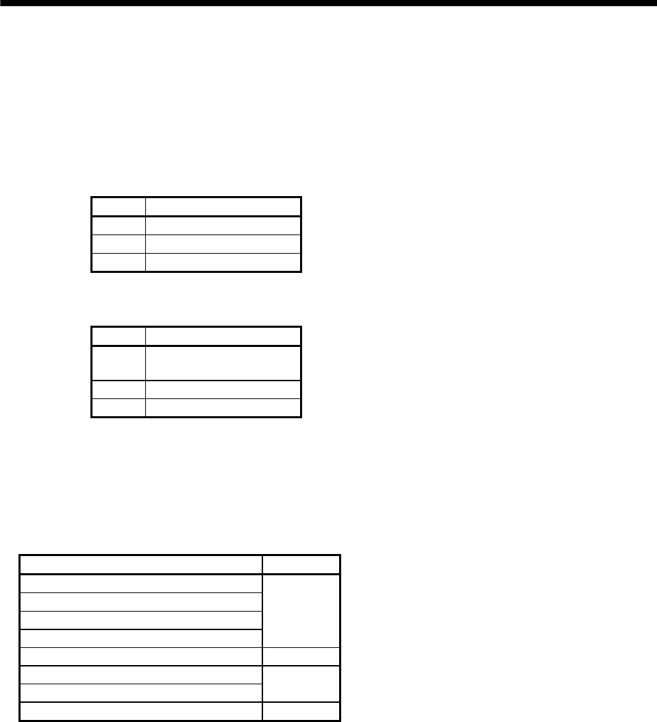
(2) Continuous latch data storage allocation
The mark detection data table (the table where the current feedback position data at the input of the mark
detection signal is stored) used by each axis allocates according to the number of continuous latch data
storages (parameter No.02B0) automatically from the lowest axis to the highest axis.
The following is an example for when continuous latch data storages is 4 points for axis 1, 1 point for axis 2,
and 2 points for axis 3.
Mark detection data table Allocation
Mark detection data table 0
Axis 1
Mark detection data table 1
Mark detection data table 2
Mark detection data table 3
Mark detection data table 4
Axis 2
Mark detection data table 5
Axis 3
Mark detection data table 6
:
: