


8 - 26
8. TANDEM DRIVE
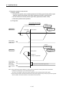
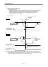
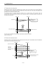
8.4.4 Automatic operation during tandem drive
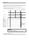
(1) Synchronous mode
When automatic operation is entered while in synchronous mode, master axis data and signals are used.
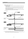
Also, the master axis table is used for the point table. An example is shown below.
ON
OFF
ON
OFF
ON
OFF
ON
OFF
ON
OFF
ON
OFF
ON
OFF
Rough match output limits
(parameter No.0230, 0231)
Stops after moving to
the end point.
Start of operation
Speed (master axis)
Speed (slave axis)
Start operation (ST)
Rough match (CPO)
(master axis)
Positioning complete
(PF) (master axis)
During operation
(OP) (master axis)
During smoothing of
stopping (SMZ)
(master axis)
Automatic operation
mode (AUT)
(master axis)
In automatic
operation mode
(AUTO) (master axis)
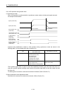
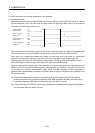
Important data classifications related to automatic operation during synchronous mode are shown in the
following table. For other related data, refer to Section 10.6.
Type
Items for which only item associated
with master is valid
Items defined for each axis
Command signal/data Automatic operation mode (AUT)
Start operation (ST)
Start point number
End point number
(Point table)
None
Status signal In automatic operation mode (AUTO)
During operation (OP)
During smoothing of stopping (SMZ)
Positioning complete (PF)
Rough match (CPO)
In-position (INP)
Position switch (PSW)
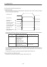
The in-position signal (INP) is output for each axis separately; therefore, when the axes have come to a
stop and in-position signals (INP) are being used, check the in-position signal (INP) for both the master axis
and the slave axis.
For other types of movement, normal axis movement is followed. (Refer to Section 5.3)
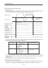
(2) Non-synchronous micro-adjustment mode
Automatic operation can not be entered while in non-synchronous micro-adjustment mode. The while in
tandem drive non-synchronous mode (operation alarm 51, detail 01) occurs upon start of operation.