


App. - 4
APPENDIX
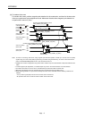
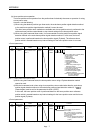
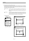
(b) For tandem drive axes
For tandem drive axes, perform magnetic pole detection for the master axis, and then for the slave axis
in the non-synchronous micro adjustment mode. Make sure the axis where magnetic pole detection is
not performed is servo off (free).
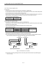
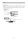
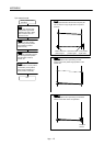
sscWaitStatusBitSignalEx function
(SSC_STSBIT_AX_RDY)
sscWaitStatusBitSignalEx function
(SSC_STSBIT_AX_ASYO )
sscSetCommandBitSignalEx funtion
(SSC_CMDBIT_AX_SON)
Magnetic pole
detection time
OFF
ON
OFF
ON
OFF
ON
OFF
ON
OFF
ON
OFF
ON
sscWaitStatusBitSignalEx function
(SSC_STSBIT_AX_RDY)
sscSetCommandBitSignalEx function
(SSC_CMDBIT_AX_SON)
Magnetic pole
detection time
sscSetCommandBitSignalEx function
(SSC_CMDBIT_AX_ASYN )
Servo On (SON)
(master) axis
Servo ready (RDY)
(master) axis
Servo On (SON)
(slave) axis
Servo ready (RDY)
(slave) axis
In non-synchronous
mode (Group )
(ASYO )
Non-synchronous
command (Group )
(ASYN )
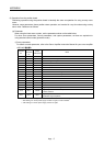
Note 1. As shown on the timing chart above, during magnetic pole detection operation, it takes up to 15s from servo-on (SON)
signal turning on to servo ready (RDY) signal turning on. Before using the API library, set 15s or more to the time-out
period in sscWaitStatusBitSignalEx function, and wait until the servo on.
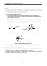
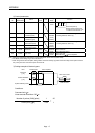
2. Establish the machine configuration using a limit switch. Collision may be caused between components without a limit
switch.
3. In initial magnetic pole adjustment, a controlled object may move in the forward direction or reverse direction.
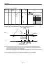
4. For tandem drive axes, do not turn servo on simultaneously for both the master and slave axes.
5. Magnetic pole detection time is the operating time when the stroke limit signal (FLS/RLS) is on.
6. When switching between non-synchronous mode/synchronous mode, check that all of the following conditions are
satisfied.
• The in-position signal (INP) is ON for both the master axis and slave axis.
• No operation alarm has occurred for both the master axis and slave axis.