


9 - 22
9. INTERFACE MODE
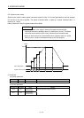
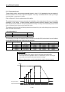
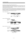
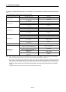
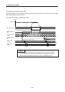
The timing of control differs depending on the settings of the command data update cycle and interrupt output
cycle.
Use the table below when referring to the timing charts.
Command data update cycle Interrupt output cycle Reference
Control cycle × 1
Control cycle × 1 Refer to (2)(a)
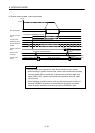
Control cycle × n
(n = 2 to 16)
(Note 2)
Control cycle × 2
Control cycle × 1 Refer to (3), (Note 1)
Control cycle × 2 Refer to (2)(b)
Control cycle × n
(n = 3 to 16)
(Note 2)
Control cycle × 3
Control cycle × 1 Refer to (3), (Note 1)
Control cycle × 2 Unavailable
Control cycle × 3 Refer to (2)(b)
Control cycle × n
(n = 4 to 16)
(Note 2)
Control cycle × 4
Control cycle × 1 Refer to (3), (Note 1)
Control cycle × 2 Refer to (3), (Note 1)
Control cycle × 3 Unavailable
Control cycle × 4
(n = 4 to 16)
Refer to (2)(b)
Control cycle × n
(n = 5 to 16)
(Note 2)
: : :
Control cycle × m
(m = 5 to 16)
Control cycle × n
(when n<m, and m is a factor of n)
Refer to (3), (Note 1)
Control cycle × n
(when n<m, and m is not a factor of n)
Unavailable
Control cycle × n
when n = m
Refer to (2)(b)
Control cycle × n
(when n>m)
(Note 2)
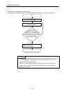
Note 1. When the update of the command is slower than the control cycle, the servo amplifier in-position signal and current feedback
position is still used when importing in a cycle shorter than the command data update is necessary.
2. When command data update cycle < interrupt output cycle, and command is updated for every interrupt output cycle, the timing
of the update of command data is still too late. For position control mode, the update of several position command buffers every
interrupt output cycle is necessary. Set the maximum buffer number so that (command data update cycle) × (maximum buffer
number + 1) > (interrupt output cycle), and perform the control method for interrupt output invalid at the timing of the interrupt
generation.
For speed control mode or torque control mode, the above setting cannot be used.