


9 - 25
9. INTERFACE MODE
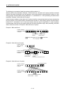
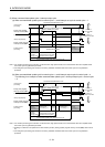
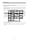
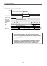
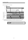
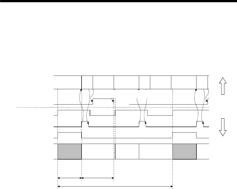
(3) When command data update cycle > interrupt output cycle
The following is an example of when command data update cycle is control cycle × 2, and interrupt output
cycle is control cycle × 1.
Using the interrupt output cycle as a reference, the user program updates the command buffer during the
command data update cycle once only. Make sure the user program occupy period is within (interrupt
output cycle) – (control cycle/2).
User program
processing
Control cycle
Interrupt signal (IRQ)
System program
processing
During user program
memory access (HMA)
During system program
memory access (BMA)
Control on
host controller
side
Control on
position board side
Realtime
processing
(Note 1)
(Command read)
System
program
occupy period
User program
occupy period
(Less than control
cycle/2)
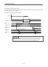
Command data update cycle=interrupt output cycle
Background
processing
(Note 3)
Realtime
processing
(Note 1)
(Command read)
Background
processing
(Note 3)
Realtime
processing
(Note 2)
Handler
Command
buffer 0 write
sscIfmRenewLatestBufferEx function
Handler Handler
sscSetCommandBitSignalEx function
(SSC_CMDBIT_SYS_HMA)
High speed
monitor etc.
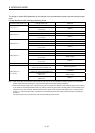
Note 1. For real time processing, the execution of command read, high speed monitor, and communication with servo amplifier within
the control cycle are guaranteed processes.
2. Reading of command is not performed for this real time process. (During system program memory access (BMA) does not turn
on)
3. For background processing, the execution of monitor, parameter read/write within the control cycle are not guaranteed
processes.