


App. - 9
APPENDIX
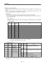
(c) Home position return process for tandem drive axes
The following shows an example of the home position return for the tandem drive axes. In this example,
the scale home position signal detection method is used as a home position method. The scale home
position signal detection method has the adjustment mode and the normal mode, which can be selected
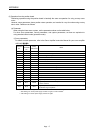
in the tandem drive options (parameter No.0265).
Adjustment mode: This mode is used, for example, during adjustment at factory shipment, and is
used to calculate the home position signal offset (amount of deviation in the
position of the home position signal for the master axis and slave axis) on a
linear scale.
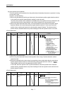
Normal mode: In this mode, the amount of deviation between the master axis and slave axis is
detected and tweaking (compensation of deviation between master axis and
slave axis) is performed. This movement sets the axis linking the master axis and
slave axis mechanically at a right angle to the movement direction.
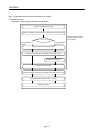
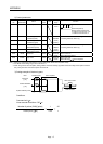
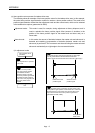
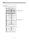
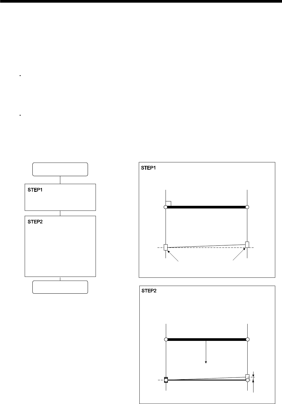
1) In adjustment mode
Home position
offset value
End
Micro-adjustment of position
of slave axis
Execution of home position
return using a home position
signal detection method
(adjustment mode). Tandem
drive home position signal offset
(parameter No.026C, 026D) is
saved on the user program side
after home position return
complete.
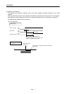
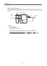
Set the axes and the joint part mechanically at a right angle.
(It is not guaranteed that the line between both home
position signals and the both axes are crossed at a right angle.)
By home position return processing, the axis moves to the
home position signal position of the master axis. At this time,
the offset amount of the master axis and the slave axis is
output to the tandem drive home position signal offset
(parameter No.026C, 026D).
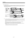
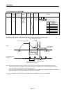
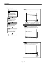
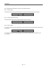
Master axis home
position signal
Slave axis home
position signal
Home position return
procedure