


1 - 10
1. SUMMARY
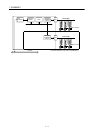
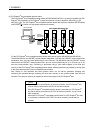
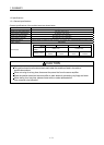
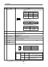
1.3.2 List of specifications of position board
(1) Position board control specifications
Function
Contents
Remarks
MR-MC210 MR-MC211 MR-MC240 MR-MC241
System
function
Control cycle 0.88ms/0.44ms/0.22ms (Select using parameters.)
Control axes Max 20 Max 32 Max 20 Max 32
Control mode Standard mode: Position controlling method by position
board
Interface mode : Sequential positioning command
method by user program
SSCNET communication SSCNET /H, SSCNET
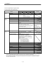
Operation
function
(Note 1, 2)
JOG operation Provided
Incremental feed Provided
Automatic operation Point table method, 1 axis control,
Continuous operation to torque control
Linear interpolation Point table method, MAX 4 axes interpolation is
available
Unavailable when the
control cycle is 0.22ms
Home position return Dog cradle method, Dog method, Data set method,
Stopper method, Limit switch combined method, Scale
home position signal detection method,
Limit switch front end method, Dog front end method,
Z-phase detection method,
Scale home position signal detection method 2
Can indicate direction
for home position return
Proximity dog is for level
detection
Can change home
position return method
while system is running
Home position reset (data set) The current position can
be reset to the home
position
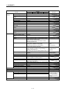
Application
function
Electronic gear
Electronic gear numerator
Electronic gear denominator
: 1 to 5242879
: 1 to 589823
Speed units Command unit/min, command unit/s, and r/min can be
selected.
Acceleration/deceleration Command speed limits: 1 to speed limit
Limits of Start speed: 1 to speed limit
Time constant limits: 0 to 20000 ms/speed limit
Separate setting of constants for deceleration and
acceleration: provided
Setting of constants for separate points: provided
Acceleration/deceleration method:
Linear acceleration/deceleration,
smoothing filter, start up speed,
S-curve acceleration/deceleration
(sine acceleration/deceleration)
Stop function Forced stop, Stop operation, Rapid stop operation
Limit switch Provided (Hardware stroke limit)
Software limit Provided (Software stroke limit)
Interlock Provided
Rough match output Provided
Torque limit Provided
Command change Location, speed, time constant
Backlash Provided
Position switch Provided
Completion of operation signal Provided
Interference check Provided Unavailable when the
control cycle is 0.22ms
Home position search limit Provided
Note 1. The position board can move within the limits of -2147483648 to 2147483647. Movement outside the limits is not covered with
warranty. If software limits have been disabled, be careful not to move it outside of the physical limits.
2. For the absolute position detection system, the command limits of the position after calculation using the electronic gear are
also -2147483648 to 2147483647. It is possible for the moveable limits to be narrower than -2147483648 to 2147483647,
depending on the electronic gear.