6 - 43
6. APPLICATION FUNCTIONS
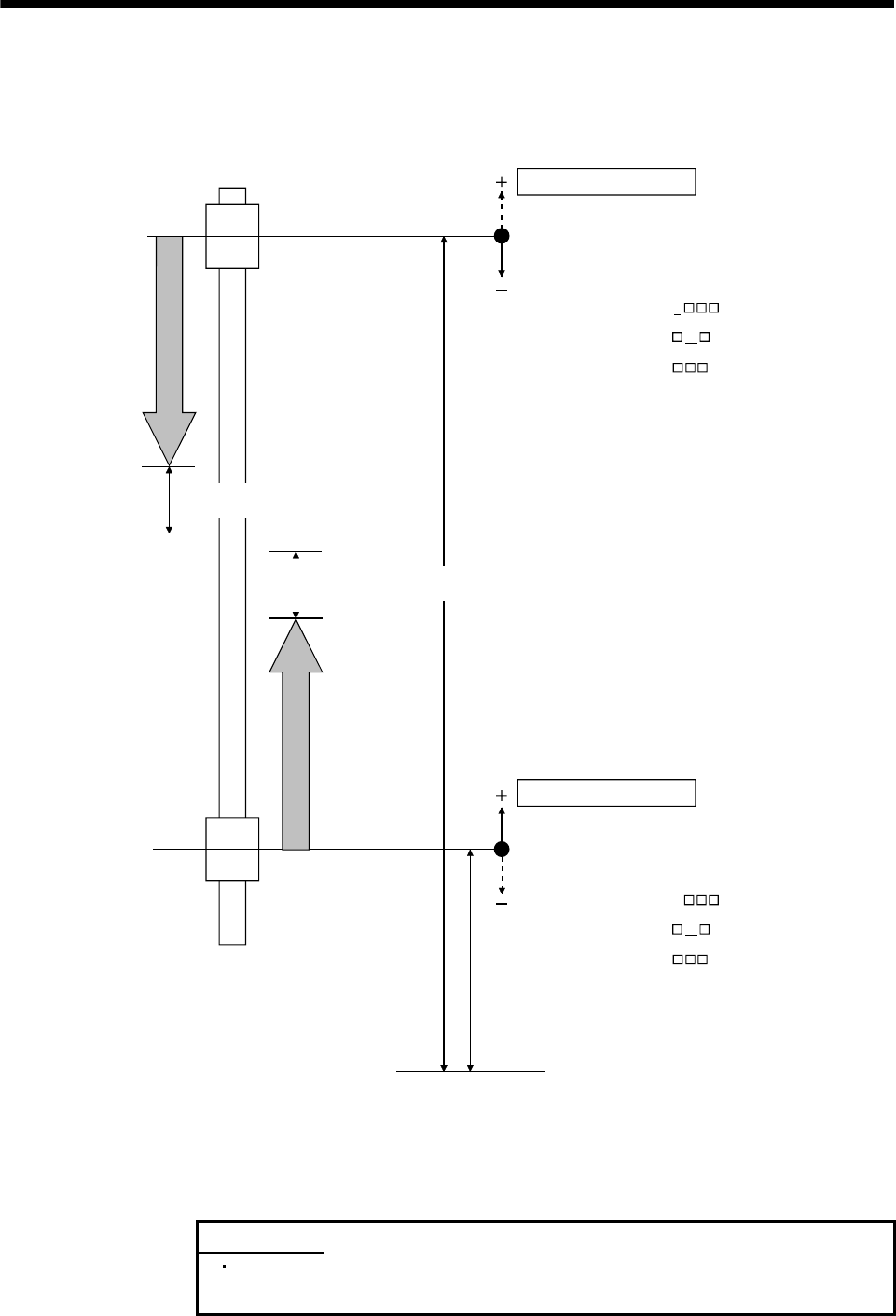
6.17.2 Interference check operation image diagram
The following example shows where the direction of the interference check coordinate (the direction of the
coordinate system for each axis against the standard coordinate system) is the same direction.
Axis 2
operation
Axis 1
operation
Axis 1
Axis 2
Axis 1 interference check offset value
(parameter No.0284, 0285)
Home position of axis 1
(where the current command position is 0)
Standard coordinate system (Note 1)
Home position of axis 2
(where the current command position is 0)
Axis 2 interference check offset value
(parameter No.0284, 0285)
Axis 2 interference check width
(parameter No.0286, 0287) (Note 2)
Axis 1 interference check width
(parameter No.0286, 0287) (Note 2)
Axis 2 coordinate system
(Note 3)
Axis 1 coordinate system
(Note 3)
Interference check direction
Interference check direction
Axis 2 interference check coordinate direction
(parameter No.0281) = 0
Axis 2 interference check axis
(parameter No.0281) = 00
Axis 2 interference check direction
(parameter No.0282) = 1
Axis 1 interference check coordinate direction
(parameter No.0281) = 0
Axis 1 interference check axis
(parameter No.0281) = 01
Axis 1 interference check direction
(parameter No.0282) = 0
Note 1. The standard coordinate system is virtual, therefore there are not any parameter settings for the
standard coordinate system itself.
2. Make sure to set the interference check width. Normally, the same value occurs for independent axes
and for interference check axes.
3. The coordinate system direction is positive (direction to which the coordinate values increase).
POINT
Interference check is valid when the travel direction is the same as the
interference check direction.


