


10 - 28
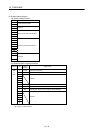
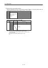
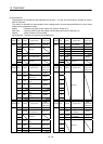
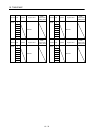
10. TABLE MAP
(2) Command bit
The addresses in the table are the addresses for the axis 1. For the axis 2 and above, increase in units of
C0h for each axis.
The column in the table for when tandem drive is being used is for axis data classification for when using
tandem drive synchronous mode.
Master : The data only valid for the master axis (refer to Section 8.3)
Each axis : The data valid for both the master axis and slave axis (refer to Section 8.3)
Special : Refer to Section 8.5 for details.
Not supported : The data not supported by tandem drive.
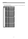
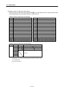
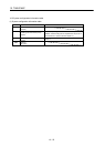
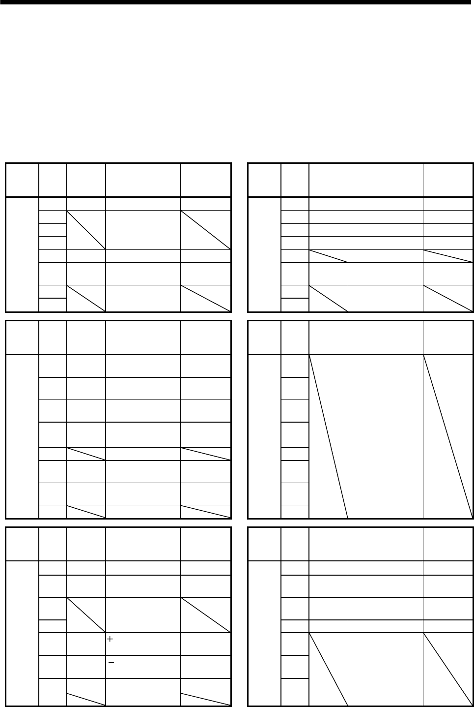
Address Bit Symbol Signal name
When
tandem drive
is being used
Address Bit Symbol Signal name
When
tandem drive
is being used
1000 0 SON Servo on Special 1001 0 ST Start operation Master
1
Reserved
1 DIR Movement direction Master
2 2 STP Stop operation Master
3 3 RSTP Rapid stop Master
4 TL Torque limit Each axis 4 Reserved
5 SRST Servo alarm reset Each axis 5 ORST
Operation alarm
reset
Master
6
Reserved
6
Reserved
7 7
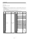
Address Bit Symbol Signal name
When
tandem drive
is being used
Address Bit Symbol Signal name
When
tandem drive
is being used
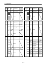
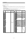
1002
0 AUT
Automatic operation
mode
Master
1003
0
Reserved
1 ZRN
Home position
return mode
Master 1
2 JOG
JOG operation
mode
Master 2
3 S
Incremental feed
mode
Master
3
4 Reserved 4
5 LIP
Linear interpolation
mode
Master 5
6 DST
Home position reset
mode
Master 6
7 Reserved 7
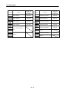
Address Bit Symbol Signal name
When
tandem drive
is being used
Address Bit Symbol Signal name
When
tandem drive
is being used
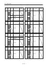
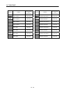
1004
0 ITL Interlock Master
1005
0 SCHG Change speed Master
1 RMONR
High speed monitor
latch command
Each axis 1 TACHG
Change acceleration
time constant
Master
2
Reserved
2 TDCHG
Change deceleration
time constant
Master
3 3 PCHG Position change Master
4 LSPC
side limit switch
input
Each axis 4
Reserved
5 LSNC
side limit switch
input
Each axis 5
6 DOGC Proximity dog input Each axis 6
7 Reserved 7