


6 - 81
6. APPLICATION FUNCTIONS
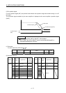
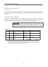
The following shows the connectors of the servo amplifier to be connected to the general input/output signals.
Each general input/output signal is assigned to the digital input signal (DI_
) and digital output signal
(DO_
). For details, refer to Section 6.27.2.
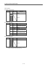
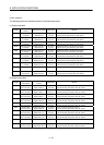
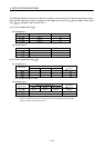
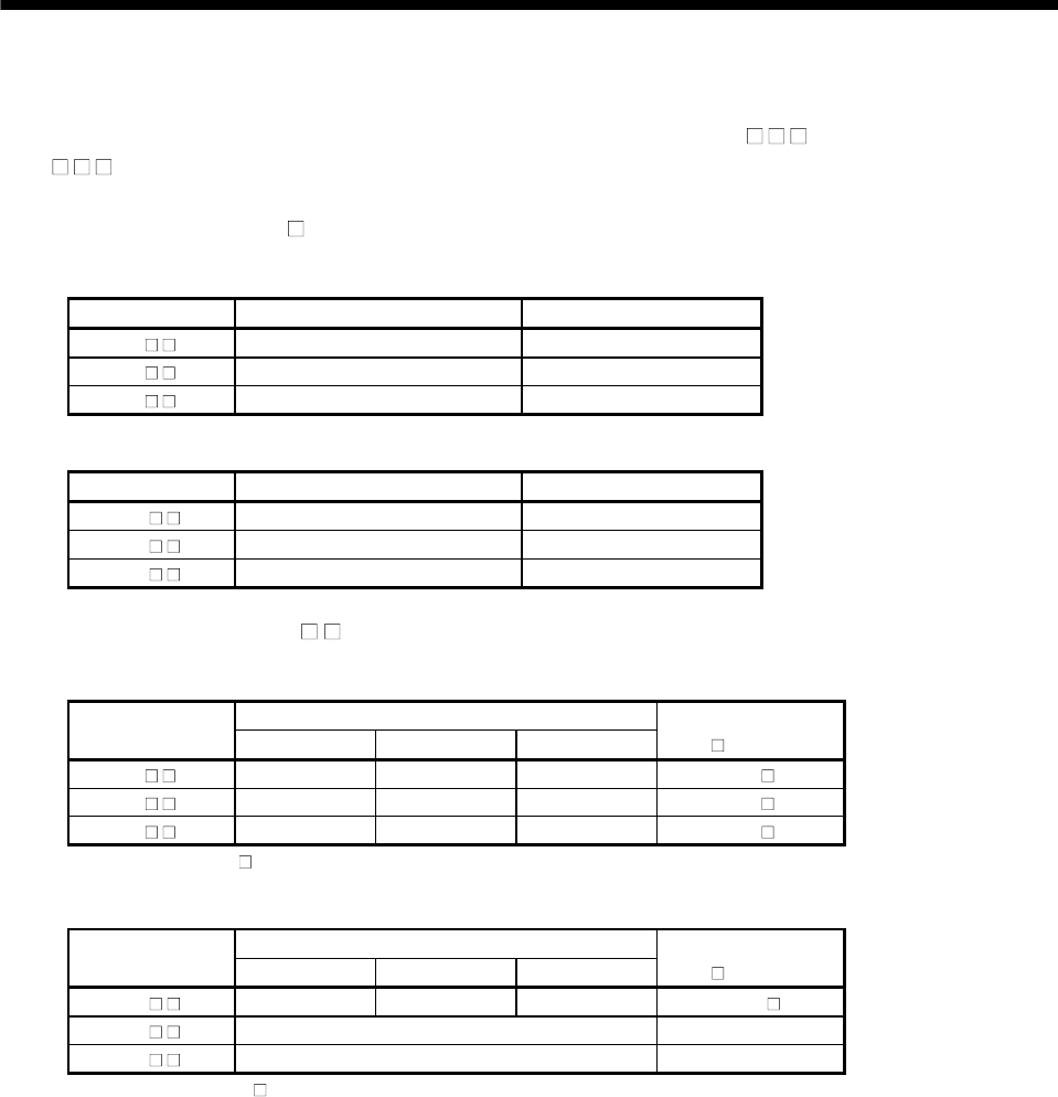
(1) For servo amplifier MR-J4-
B
(a) General input
Signal name Destination connector pin No. Abbreviation
DI_ 0 CN3-2 DI1
DI_ 1 CN3-12 DI2
DI_ 2 CN3-19 DI3
(b) General output
Signal name Destination connector pin No. Abbreviation
DO_ 0 CN3-13 MBR
DO_ 1 CN3-9 INP
DO_ 2 CN3-15 ALM
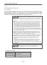
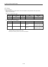
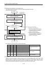
(2) For servo amplifier MR-J4W
- B
(a) General input
Signal name
Destination connector pin No.
Abbreviation
(
: A, B, C)
Axis A Axis B Axis C (Note)
DI_ 0 CN3-7 CN3-20 CN3-1 DI1-
DI_ 1 CN3-8 CN3-21 CN3-2 DI2-
DI_ 2 CN3-9 CN3-22 CN3-15 DI3-
Note: Only MR-J4W3- B is available.
(b) General output
Signal name
Destination connector pin No.
Abbreviation
(
: A, B, C)
Axis A Axis B Axis C (Note1)
DO_ 0 CN3-12 CN3-25 CN3-13 MBR-
DO_ 1 CN3-11 (Note2) CALM
DO_ 2 CN3-24 (Note2) CINP
Note 1. Only MR-J4W3- B is available.
2. The pin is common for each axis. The axis to be used can be selected by the parameter
setting. For details, refer to Section 6.27.2.