


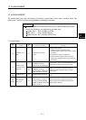
13 - 5
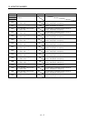
13. ALARM NUMBER
Alarm
No.
Content
Detail
No.
Cause of occurrence Procedure
2E
Control mode
switch error
01
Control mode was changed during
operation.
When changing from position control mode to
speed control mode/torque control mode, or
changing from speed control mode/torque control
mode to position control mode, perform the
control mode change while stopped.
02
A control mode outside of setting range
was set.
Reexamine the value of the control mode
command.
03
(Note)
Without the control mode changing, a time
out occurred.
(1) If the control mode change was conducted on
an axis that does not support control mode
change, check that control mode change is
possible before performing a control mode
change.
(2) An error occurred in communication
processing between the position board and the
servo amplifier. Make contact with and explain
the failure symptoms to an agency or branch
office.
04
During standard mode, a switch command
to a control mode that cannot be switched
to was input.
Reexamine the value of the control mode
command. (a value that is not speed control
mode, torque control mode, or outside of range)
2F
Torque control
setting error
01
A value outside of range is set to the
torque control speed limit value.
Reexamine the value of the torque control speed
limit value.
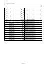
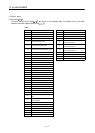
37
(Note)
Parameter error 01 Parameter setting is erroneous.
Set the setting to correct value within the
parameter limits.
38
(Note)
System setting
error
01
The setting for the control axis exceeds the
maximum number of control axes.
Reexamine the structure of the system.
02
When Axis No. assignment is valid, the
servo amplifier axis No. (parameter
No.0203) is set to 0.
Set the axis No. to the servo amplifier axis No.
(parameter No.0203).
03
When Axis No. assignment is valid, the
setting value of the servo amplifier axis No.
(parameter No.0203) is out of range of the
valid axis number.
Set the axis No. within the valid range to the servo
amplifier axis No. (parameter No.0203).
04
When Axis No. assignment is valid, the
setting value of the servo amplifier axis No.
(parameter No.0203) is the same as other
axes.
Reexamine of the setting of the servo amplifier
axis No. (parameter No.0203).
39
(Note)
Input/output
number
assignment error
01
The general input number assigned to the
digital input table is the same as the setting
for other servo amplifiers. Or, the
assignment exceeds its allowable range.
Reexamine the general input/output number
assignment setting (parameter No.0214) for the
servo amplifier.
02
The general output number assigned to the
digital output table is the same as the
setting for other servo amplifiers. Or, the
assignment exceeds its allowable range.
Reexamine the general input/output number
assignment setting (parameter No.0214) for the
servo amplifier.
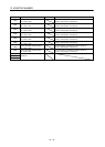
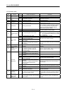
3B
(Note)
Mark detection
setting error
01
Mark detection was enabled in a
communication mode that is not
compatible.
Use mark detection in a SSCNET
/H system.
02
Mark detection function is set to enabled
for an axis that does not support mark
detection function.
(1) Change the servo amplifier being used to an
axis with a mark detection signal function.
(2) Disable the mark detection settings.
03
When the mark detection mode is ring
buffer, the number of continuous latch
storages was set to 0.
Reexamine the value of number of continuous
latch data storages (parameter No.02B0,
No.02B2).
04
Mark detection function was set to enabled
for an axis that is set to get sensor input
from driver.
(1) Reexamine the setting of sensor input option
(parameter No.0219).
(2) Disable the mark detection settings.
Note. The operation alarm cannot be reset.