


9 - 16
9. INTERFACE MODE
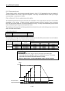
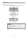
9.5.4 Torque control mode
Torque control mode is where torque commands (torque in units of 0.1%) generated by the user program of
the host controller can be sent to the servo amplifier. The torque command buffer is made up of torque
command data × a maximum of 1 buffer.
Refer to Section 9.5.6 for the update method of the buffer.
The relationship between the torque command and the direction of the output torque of the servo motor differs
depending on the settings of rotation direction selection/movement direction selection (servo parameter
No.110D) and function selection C-B (servo parameter No.119C). The torque command during torque control
mode is restricted by the torque control speed limit value.
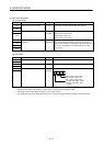
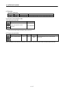
The meanings of the signs for the following data that can referred to by the monitor during torque control mode
differ from other control modes.
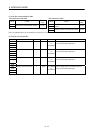
• Servo information (2)
Monitor No. Content Units
020A Electrical current command
0.1%
020B Electrical current feedback 0.1%
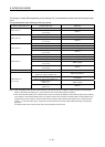
The meanings of the signs for electrical current command (monitor No.020A) and electrical current feedback
(monitor No.020B) during torque control mode are as follows.
Parameter No. Command direction
Motor revolution
direction
Electrical current command/electrical current feedback sign
Position control Speed control Torque control
0
Positive CCW (positive) Positive Positive Positive
Negative CW (negative) Negative Negative Negative
1
Positive CW (negative) Negative Negative Positive
Negative CCW (positive) Positive Positive Negative
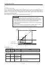
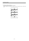
POINT
• If a value outside of the range is input to the torque command buffer,
command data error (operation alarm A7, detail No.02) occurs. The torque
command value becomes the value before the change.
• When an alarm occurs, conduct a deceleration stop by the user program.
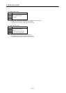
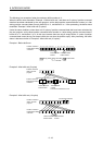
Zero speed (ZSP)
Torque command data
0 10 20 30
30.0%
Torque
300 to 030030 to 300 0