


6 - 104
6. APPLICATION FUNCTIONS
6.30 Mark detection
6.30.1 Summary
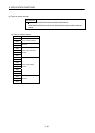
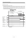
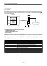
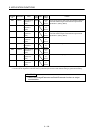
Mark detection is a function that gets the positioning data at the timing of when a mark detection signal is input
to the servo amplifier, and outputs to the dual port memory. This function is compatible with SSCNET
/H
communication method only.
BAF0h
BB2Fh
BB30h
BC2Fh
Mark detection edge
data table
64 bytes
(1 data-1 byte)
Dual port memory
Mark detection position
data table
256 bytes
(1 data-4 bytes)
Position board
SSCNET communication
Positioning data
Mark detection signal
(external signal)
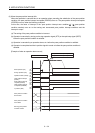
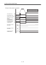
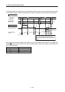
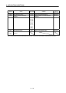
Three methods for mark detection modes can be selected.
• Continuous detection mode
• Specified number of detection mode
• Ring buffer mode
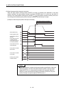
Additionally, the range of the mark detection positioning data can be specified, so only data within the specified
range is latched.
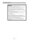
When interrupt conditions 2 (parameter No.0205) is enabled and mark detection signal is detected, an interrupt
can be generated. However, when not using the interrupt, or in interface mode, the mark detection counter
must be monitored at all times.
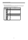
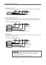
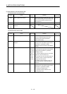
Item Performance specifications
Number of mark detection settings Up to 2 settings for each axis
Input signal External input signal (within DI1 to DI3, 2 points) of each servo amplifier
Input signal detection direction Leading edge/trailing edge detection in logic setting (ON edge detection setting,
OFF edge detection setting) of external input signal can be selected
Detection accuracy 55µs (input signal filter (0 to 444 µs) can be selected in parameter setting)
Detection delay 0.3ms or less + filter setting value (0 to 0.444ms)
Note. Sensor delay time is not included
Input signal minimum width 0.88ms (make ON/OFF width 0.88ms or more)
Latch data 2 types (current feedback position [command units], current feedback position [pulse])
Number of continuous latch data storages Up to 64 (the whole system)
Latch data range Within the range of -2147483648 to 2147483647 can be specified