


9 - 9
9. INTERFACE MODE
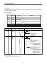
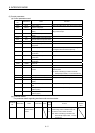
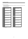
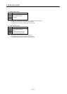
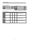
(5) Position command buffer
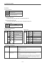
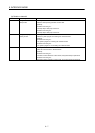
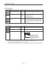
The number of buffers and the addresses that are used differ for each control mode. The buffers for each
control mode are shown below.
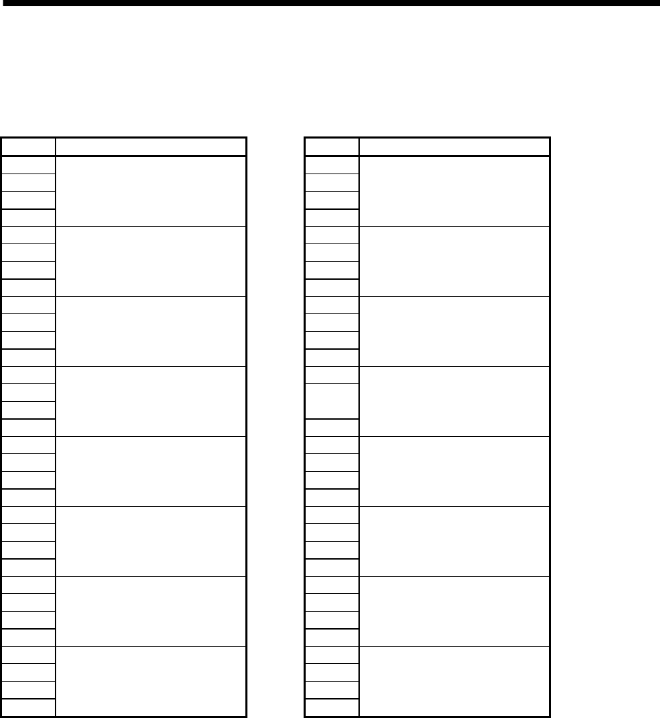
(a) Position control mode
Address Content Address Content
5000
Position command buffer 0
(pulse)
5020
Position command buffer 8
(pulse)
5001 5021
5002 5022
5003 5023
5004
Position command buffer 1
(pulse)
5024
Position command buffer 9
(pulse)
5005 5025
5006 5026
5007 5027
5008
Position command buffer 2
(pulse)
5028
Position command buffer 10
(pulse)
5009 5029
500A 502A
500B 502B
500C
Position command buffer 3
(pulse)
502C
:
500D
:
500E
500F 50EF
5010
Position command buffer 4
(pulse)
50F0
Position command buffer 60
(pulse)
5011 50F1
5012 50F2
5013 50F3
5014
Position command buffer 5
(pulse)
50F4
Position command buffer 61
(pulse)
5015 50F5
5016 50F6
5017 50F7
5018
Position command buffer 6
(pulse)
50F8
Position command buffer 62
(pulse)
5009 50F9
501A 50FA
501B 50FB
501C
Position command buffer 7
(pulse)
50FC
Position command buffer 63
(pulse)
501D 50FD
501E 50FE
501F 50FF
Note. The addresses in the table are the addresses for the axis 1. For the axis 2 and above, increase the units of
100h for each axis.