


4 - 5
4. SYSTEM STARTUP
POINT
• For each switch setting, refer to the Servo Amplifier Instruction Manual for
your servo amplifier.
• If the "An axis that has not been mounted exists" (system error E400)
occurred, the axis with wrong axis No. set can be confirmed with "information
concerning axis that is not mounted" (monitor No.0480 to 0482).
• The servo amplifier axis No. and the axis No. to be managed on the position
board are different. For details, refer to Section 4.5.5.
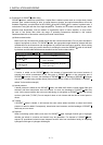
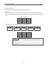
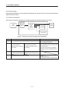
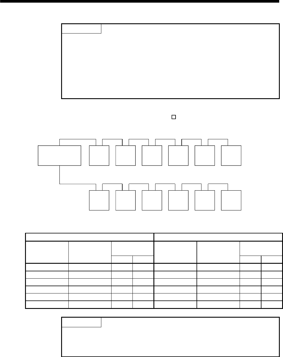
The following is a setting example for controlling six axes (MR-J4-
B) for each line by control cycle 0.88ms
using MR-MC211.
Position board
Servo
amplifier
d15
d16 d1 d2 d5 d6
Servo
amplifier
Servo
amplifier
Servo
amplifier
Servo
amplifier
Servo
amplifier
Servo
amplifier
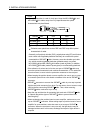
d17
d16 d1 d2 d5 d6
Servo
amplifier
Servo
amplifier
Servo
amplifier
Servo
amplifier
Servo
amplifier
Line 1
Line 2
Line 1 Line 2
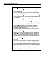
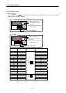
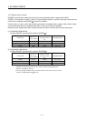
Servo amplifier
axis No.
Axis selection
rotary switch
Axis No. auxiliary
setting switch
Servo amplifier
axis No.
Axis selection
rotary switch
Axis No. auxiliary
setting switch
3 4 3 4
d15 E OFF OFF d17 0 OFF ON
d20 3 OFF ON d16 F OFF OFF
d1 0 OFF OFF d1 0 OFF OFF
d2 1 OFF OFF d2 1 OFF OFF
d5 4 OFF OFF d5 4 OFF OFF
d6 5 OFF OFF d6 5 OFF OFF
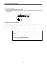
POINT
• The servo amplifier axis No. may be in no particular order, and can be
arbitrarily selected between d1 to d20.
• No. of connectable servo amplifiers vary by control cycle.