8 - 21
8. TANDEM DRIVE
2) Operation example for adjustment mode
a) Start operation method
1. Adjust the axis linking the master axis and slave axis mechanically at a right angle to the
movement direction.
2. Set the home position return method (parameter No.0240) to scale home position signal
detection method and tandem drive option (parameter No.0265) to adjustment mode.
3. Start home position return operation.
4. After home position return is complete, read the tandem drive home position signal offset
(parameter No.026C, 026D) and save it to the user program.
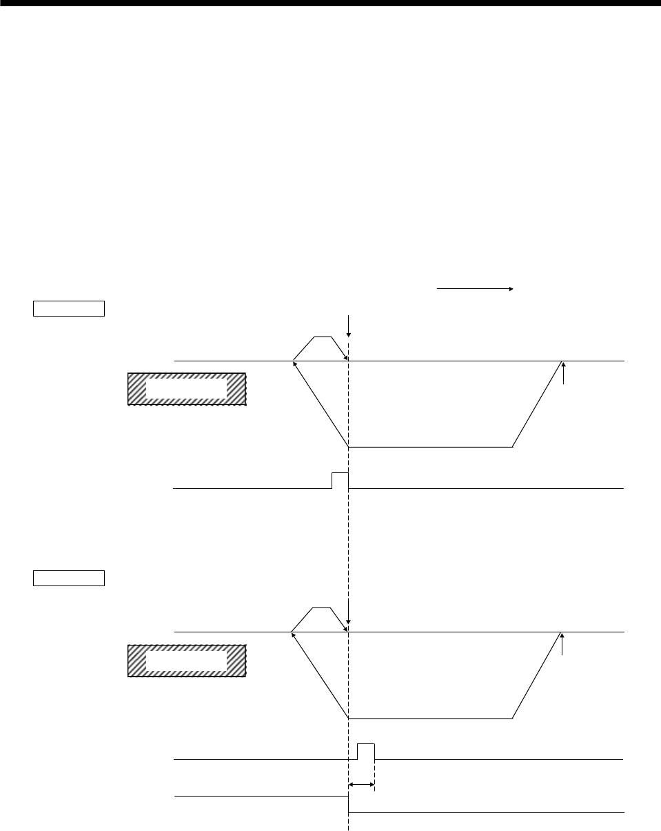
b) Timing chart
Home position signal
(Z-phase)
(master axis)
Home position signal
(Z-phase) (slave axis)
Home position
return complete
(ZP)
Master Axis Home position
Creep speed
Home position return speed
Home position return direction
Tandem drive home position signal offset
Home position
Start operation
(Note 2)
ON
OFF
ON
OFF
ON
OFF
Limit switch
(Note 1)
Limit switch
(Note 1)
Start operation
(Note 2)
Slave Axis
Note 1. When a limit switch signal is detected, an alarm occurs and execution of return to home position is terminated.
2. Set the distance between the master axis/slave axis home position signals and the start operation position so that it is
greater than the deviation at maximum tolerance of the master axis and slave axis.


