4-13
MEMORY PARTITIONS
4.2.1 Selecting a Window
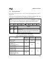
The window selection register (Figure 4-3) selects a window to be mapped into the top of the low-
er register file.
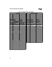
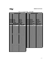
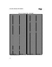
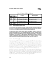
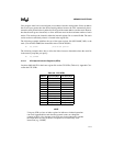
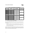
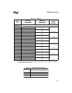
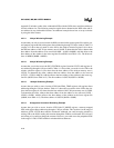
Table 4-9 provides a quick reference of WSR values for windowing the peripheral SFRs. Table
4-10 on page 4-14 lists the WSR values for windowing the upper register file.
WSR
Address:
Reset State:
0014H
00H
The window selection register (WSR) maps sections of RAM into the top of the lower register file, in
32-, 64-, or 128-byte increments. PUSHA saves this register on the stack and POPA restores it.
7 0
— W6 W5 W4 W3 W2 W1 W0
Bit
Number
Bit
Mnemonic
Function
7 — Reserved; for compatibility with future devices, write zero to this bit.
6:0 W6:0 Window Selection
These bits specify the window size and number. See Table 4-9 on page
4-13 or Table 4-10 on page 4-14. See Table 4-9 for peripheral SFR windows
or Table 4-10 for upper register file windows.
Figure 4-3. Window Selection (WSR) Register
Table 4-9. Selecting a Window of Peripheral SFRs
Peripherals
WSR Value for
32-byte Window
(00E0–00FFH)
WSR Value for
64-byte Window
(00C0–00FFH)
WSR Value for
128-byte Window
(0080–00FFH)
Port 2
Waveform generator
Port 7 (MD only)
7EH 3FH
1FH
Peripheral interrupts
Pulse-width modulator
A/D converter
Frequency generator (MD only)
Reset control (MH only)
7DH
3EH
Port 1 (MH only)
Serial I/O port (MH only)
7CH
Timer 1–2
EPA compare 2–3 (MC)
EPA compare 0–5 (MD)
EPA compare 0–2 (MH)
7BH
3DH 1EH
EPA capture/compare 0–3 (MC)
EPA compare 0–1 (MC)
EPA capture/compare 0–5 (MD)
EPA capture/compare 0–1 (MH)
EPA compare 3 (MH)
7AH


