8XC196MC, MD, MH USER’S MANUAL
5-30
5.6.4 Block Transfer Mode
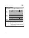
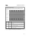
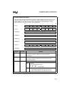
In block transfer mode, an interrupt causes the PTS to move a block of bytes or words from one
memory location to another. See AP-483, Application Examples Using the 8XC196MC/MD Mi-
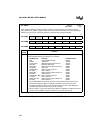
crocontroller, for application examples with code. Figure 5-17 shows the PTS control block for
block transfer modes.
In this mode, each PTS cycle consists of the transfer of an entire block of bytes or words. Because
a PTS cycle cannot be interrupted, the block transfer mode can create long interrupt latency. The
worst-case latency could be as high as 500 states, if you assume a block transfer of 32 words from
one external memory location to another, using an 8-bit bus with no wait states. See Table 5-4 on
page 5-12 for execution times of PTS cycles.
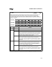
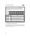
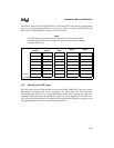
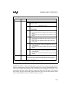
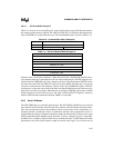
The PTSCB in Table 5-6 sets up three PTS cycles that will transfer five bytes from memory loca-
tions 20–24H to 6000–6004H (cycle 1), 6005–6009H (cycle 2), and 600A–600EH (cycle 3). The
source and destination are incremented after each byte transfer, but the original source address is
reloaded into PTSSRC at the end of each block-transfer cycle. In this routine, the PTS always gets
the first byte from location 20H.
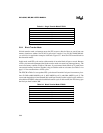
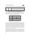
Table 5-5. Single Transfer Mode PTSCB
Unused
Unused
PTSDST (H) = 60H
PTSDST (L) = 00H
PTSSRC (H) = 00H
PTSSRC (L) = 20H
PTSCON = 85H (Mode = 100, BW = 0, SI/SU = 0, DI/DU = 1)
PTSCOUNT = 09H
Table 5-6. Block Transfer Mode PTSCB
Unused
PTSBLOCK = 05H
PTSDST (H) = 60H
PTSDST (L) = 00H
PTSSRC (H) = 00H
PTSSRC (L) = 20H
PTSCON = 17H (Mode = 000; DI, SI, DU, BW = 1; SU = 0)
PTSCOUNT = 03H


