5-43
STANDARD AND PTS INTERRUPTS
5.6.6.1 Synchronous SIO Transmit Mode Example
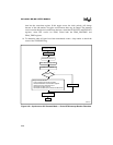
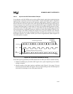
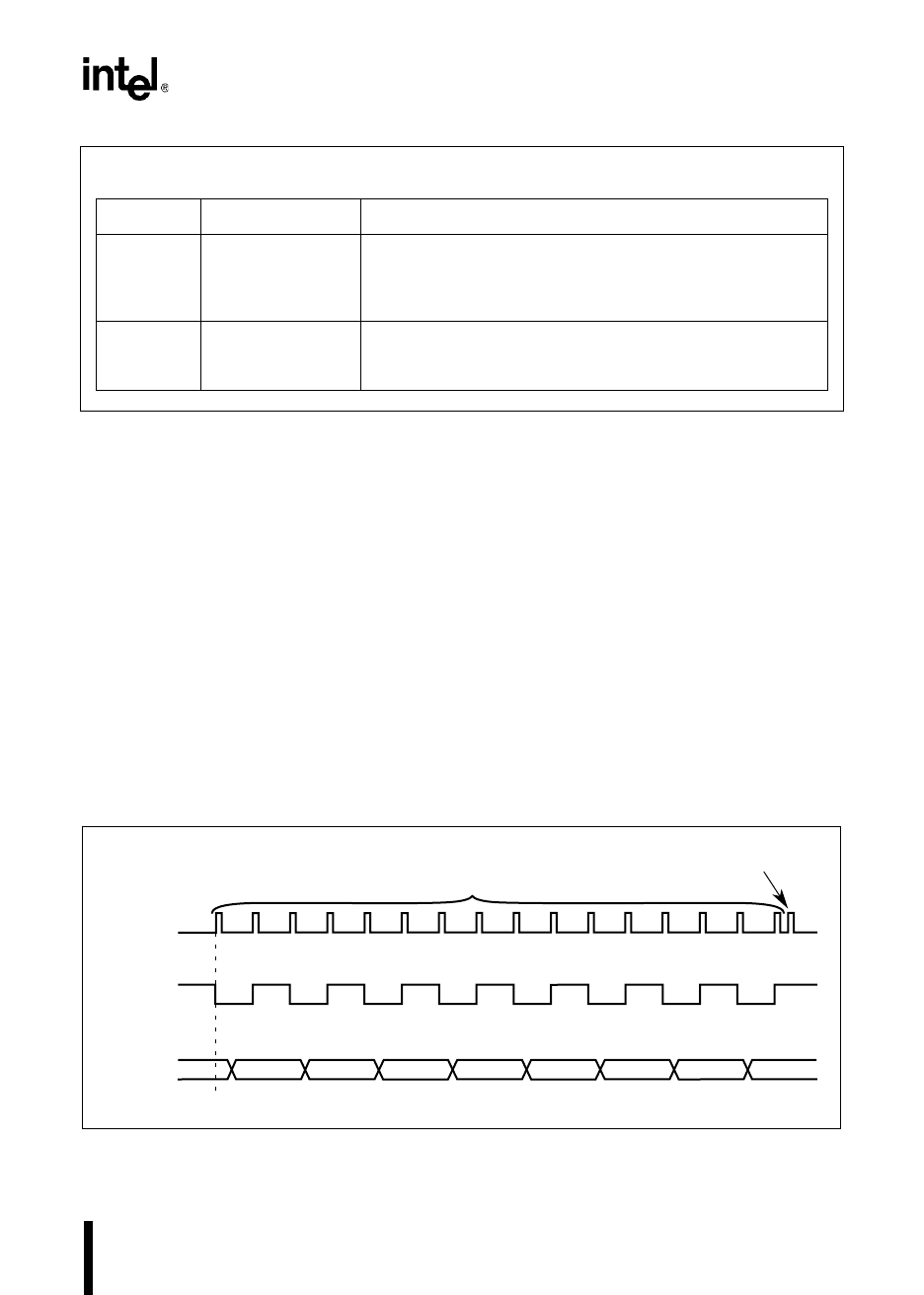
In synchronous serial I/O (SSIO) transmit mode, an EPA channel controls the transmission baud
rate by generating or capturing a serial clock signal (SCK). To generate the SCK signal, configure
the EPA channel in compare mode and set the output-pin toggle option. Whenever a match occurs
between the EPA event-time register and a timer register, the EPA channel toggles SCK and gen-
erates an interrupt. If an external source will provide the SCK signal, configure the EPA channel
in capture mode with capture on either edge set. In this case, the EPA channel generates an inter-
rupt whenever the SCK input toggles. On every other EPA interrupt, the PTS shifts a data bit out
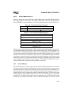
onto a port pin that is configured to function as the Transmit Data signal (TXD). PTSCON1 (Fig-
ure 5-19 on page 5-38) controls whether the transmission occurs on even or odd PTS cycles. Be-
cause transmissions occur only on a rising or falling clock edge, two PTS cycles occur for every
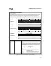
one data bit transmission (Figure 5-21). It takes 16 PTS cycles to transmit eight data bits. In SSIO
transmit mode, only data bits can be transmitted; parity and stop bits are not included.
Figure 5-21. Synchronous SIO Transmit Mode Timing
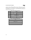
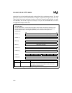
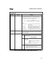
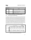
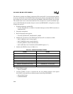
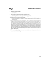
Register Location Function
PORTMASK PTSCB2 + 2 Port Mask Register
Select the port signal that will function as the transmit data (TXD)
or receive data (RXD) signal by setting the corresponding bit.
Clear all other bits to mask those signals.
PORTREG PTSCB2 + 0 Port Address Pointer
This 16-bit register contains the address of the port that will be
used to transmit or receive data.
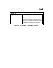
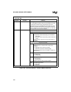
PTS Serial I/O Mode Control Block 2 (Continued)
(8XC196MC, MD)
Figure 5-20. PTS Control Block 2 – Serial I/O Mode (Continued)
A3120-01
Interrupts
Bit 0 Bit 1 Bit 2 Bit 3 Bit 4 Bit 5 Bit 6
Bit 7
End-of-PTS
Conventional
Interrupt
16 PTS Serviced Interrupts
LSB MSB
SCK
TXD
(Port pin)


