16-19
PROGRAMMING THE NONVOLATILE MEMORY
16.8.4 Slave Programming Routines
The slave programming mode algorithm consists of three routines: the address/command decod-
ing routine, the program word routine, and the dump word routine.
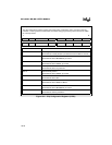
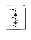
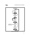
The address/command decoding routine (Figure 16-7) reads the PBUS and transfers control to
the program word or dump word routine based on the value of P3.0. A one on P3.0 selects the
program word command and the remaining bits specify the address. For example, a PBUS value
of 3501H programs a word of data at location 3500H. A zero on P3.0 selects the dump word com-
mand and the remaining bits specify the address. For example, a PBUS value of 3500H places
the word at location 3500H on the PBUS.
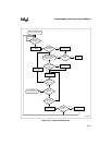
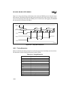
The program word routine (Figure 16-8) checks the CCB security-lock bits. If either security lock
bit (CCB0.6 or CCB0.7) has been programmed, you must provide a matching security key to gain
access to the device. Using the program word command, write eight consecutive words to the de-
vice, starting at location 2020H and continuing to 202FH. The routine stores these eight words in
an internal register and compares their value with the internal key. If the keys match, the routine
allows you to program individual or sequential OTPROM locations; otherwise, the device enters
an endless loop.
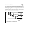
The dump word routine (Figure 16-10) also checks the CCB security-lock bits, but it has no pro-
vision for security key verification. If the lock bits are unprogrammed, the routine fetches a word
of data from the OTPROM and writes that data to the PBUS. If either lock bit is programmed, the
routine performs a write cycle without first getting data from the OTPROM.


