9-21
WAVEFORM GENERATOR
9.7.2 EXTINT Interrupts and Protection Circuitry
The protection register contains two bits, disable protection (DP) and enable output (EO), that to-
gether enable and disable the waveform generator’s outputs. The EXTINT event generates a sin-
gl
e short pulse that clears the EO bit, so if software sets the EO bit immediately following an
EX
TINT event, the outputs will be disabled only for the time between the EXTINT event and the
CPU write. The CPU can immediately set the EO bit again, even if the EXTINT signal remains
as
serted.
9.
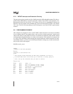
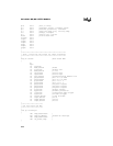
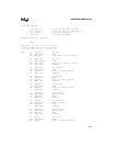
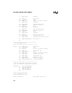
8 PROGRAMMING EXAMPLE
Th
is example was designed to run on an 8XC196MC demo board, but it can easily be modified
for an evaluation board. The program allows you to test the waveform generator’s registers and
observe their effects on the output waveforms. All variables are defined as words and are masked
to
the appropriate length before they are written to the registers. (This method is not compact, but
it is easy to code and debug.) When running the program under the reduced instruction set mon-
itor (RISM) software, you can use the following command to change any variable and immedi-
ately see the result on the outputs:
WORD.variable_name
$debug
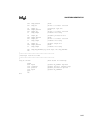
;Program to test WFG
peripheral
;
$nolist
$include (c:\ecm\196m
c\mc.inc)
$list
;
; This program allows
modifying the WFG input parameters "on the fly"
; on the MC demo boar
d. This allows you to see what is really going on.
;
; First, set up the v
ariables that you want to control:
;
rseg at 40h
;
mode
: dsw 1 ;mode = 0-3
op0
: dsw 1 ;P6.0,2,4 polarity--0=low, 1=high
op1
: dsw 1 ;P6.1,3,5 polarity--0=low, 1=high
sync
: dsw 1 ;0=load now, 1 = synchronized
pe7
: dsw 1 ;P6.7 0=i/o, 1=PWM
pe6
: dsw 1 ;P6.6 0=i/o, 1=PWM
p7
: dsw 1 ;P6.7 I/O value
p6
: dsw 1 ;P6.7 I/O value
ph1
: dsw 1 ;P6.0,1 config
ph2
: dsw 1 ;P6.2,3 config


