8XC196MC, MD, MH USER’S MANUAL
9-20
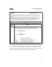
To enable the interrupts, set the corresponding mask bits in the mask register (see Table 9-2 on
page 9-3) and execute the EI instruction to enable interrupt servicing. You can read the interrupt
pending register to determine whether there are any pending interrupts. Refer to Chapter 5, “Stan-
dard and PTS Interrupts” for details.
9.7 DESIGN CONSIDERATIONS
This section describes design and programming considerations for using the waveform generator.
9.7.1 Dead Time and Duty Cycle
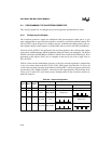
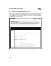
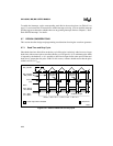
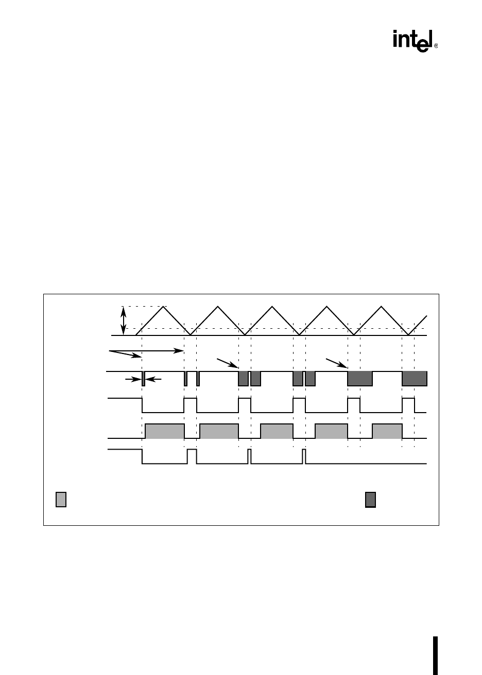
Short dead times have little effect on the duty cycle if the pulse is relatively wide; however, longer
dead times with narrower pulses can affect the duty cycle (Figure 9-14). No minimum pulse width
is imposed by the hardware, so it is possible to deassert an output for the entire period if the total
dead time is greater than the pulse width. For this reason, software should ensure that the pulse
width is at least 3 × T
DEAD
.
Figure 9-14. Effect of Dead Time on Duty Cycle
WG_COUNT
1
A2660-01
WG_COUNT=
WG_COMP
WFG
P6.0 / WG1#
=DT x WFG#
Mode 0, OP0 = OP1 = 1, PH1.0 = PH1.1 = PH1.2 = 1
Dead Time
(DT)
Dead Time
Increased
Dead Time
Increased
P6.1 / WG1
=DT x WFG
No WFG1 Output
= Power Output Driver Enabled
= Dead Time


