12-1
CHAPTER 12
ANALOG-TO-DIGITAL (A/D) CONVERTER
The analog-to-digital (A/D) converter can convert an analog input voltage to a digital value and
set the A/D interrupt pending bit when it stores the result. It can also monitor a pin and set the
A/D interrupt pending bit when the input voltage crosses over or under a programmed threshold
voltage. This chapter describes the A/D converter and explains how to program it.
12.1 A/D CONVERTER FUNCTIONAL OVERVIEW
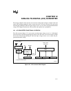
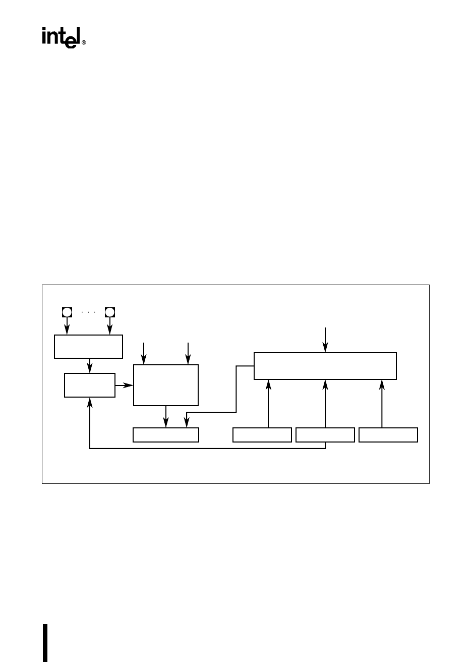
The A/D converter (Figure 12-1) can convert an analog input voltage to an 8- or 10-bit digital
result and set the A/D interrupt pending bit when it stores the result. It can also monitor an input
and set the A/D interrupt pending bit when the input voltage crosses over or under the pro-
grammed threshold voltage.
Figure 12-1. A/D Converter Block Diagram
Analog Mux
A2652-02
Successive
Approximation
A/D
Converter
Sample
and Hold
V
REF
EPA or PTS
Command
Control
Logic
AD_RESULT AD_COMMAND AD_TIME AD_TEST
ANGND
Status
† Multiplexed with port inputs
Analog Inputs
†


