7-7
SERIAL I/O (SIO) PORT
In mode 4, writing to SBUFx_TX starts a transmission regardless of whether RXDx is enabled.
However, RXDx must be enabled to allow a reception. If RXDx is enabled, either a rising edge
on the RXDx input or clearing the receive interrupt (RI) flag starts a reception.
Disabling RXDx stops a reception in progress and inhibits further receptions. To avoid a partial
or undesired complete reception, disable RXDx before clearing the RI flag. This can be handled
in an interrupt environment by using software flags or in straight-line code by using the interrupt
pending register to signal the completion of a reception.
During a reception, the RI flag is set one clock bit time after the last data bit is received. The re-
ceive interrupt signal is generated immediately before the RI flag is set. During a transmission,
the TI flag is set immediately after the end of the last (eighth) data bit is transmitted. The transmit
interrupt signal is generated when the TI flag is set.
7.3.2 Asynchronous Modes (Modes 1, 2, and 3)
Modes 1, 2, and 3 are full-duplex serial transmit/receive modes, meaning that they can transmit
and receive data simultaneously. Mode 1 is the standard 8-bit, asynchronous mode used for nor-
mal serial communications. Modes 2 and 3 are 9-bit asynchronous modes typically used for in-
terprocessor communications (see “Multiprocessor Communications” on page 7-9). In mode 2,
the serial port sets an interrupt pending bit only if the ninth data bit is set. In mode 3, the serial
port always sets an interrupt pending bit upon completion of a data transmission or reception.
When the serial port is configured for mode 1, 2, or 3, writing to SBUFx_TX causes the serial
port to start transmitting data. New data placed in SBUFx_TX is transmitted only after the stop
bit of the previous data has been sent. A falling edge on the RXDx input causes the serial port to
begin receiving data if RXDx is enabled. Disabling RXDx stops a reception in progress and in-
hibits further receptions. (See “Programming the Control Register” on page 7-10.)
7.3.2.1 Mode 1
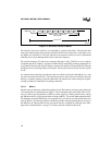
Mode 1 is the standard asynchronous communications mode. The data frame used in this mode
(Figure 7-4) consists of ten bits: a start bit (0), eight data bits (LSB first), and a stop bit (1). If
parity is enabled, a parity bit is sent instead of the eighth data bit, and parity is checked on recep-
tion.


