11-15
EVENT PROCESSOR ARRAY (EPA)
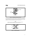
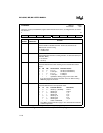
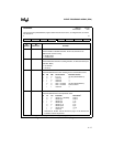
With this method, the resolution of the EPA (selected by the TxCONTROL registers; see Figure
11-8 on page 11-16 and Figure 11-9 on page 11-17) determines the maximum PWM output fre-
quency. (Resolution is the minimum time required between consecutive captures or compares.)
When the input frequency on XTAL1 is 16 MHz, a 250 ns resolution results in a maximum PWM
of 4 MHz.
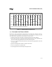
11.5 PROGRAMMING THE EPA AND TIMER/COUNTERS
This section discusses configuring the port pins for the EPA and the timer/counters; describes
how to program the timers, the capture/compare channels, and the compare-only channels; and
explains how to enable the EPA interrupts.
11.5.1 Configuring the EPA and Timer/Counter Signals
Before you can use the EPA, you must configure the appropriate port signals to serve as the spe-
cial-function signals for the EPA and, optionally, for the timer/counter clock source and direction
control signals. See “Bidirectional Ports 1 (MH Only), 2, 5, and 7 (MD Only)” on page 6-4 for
information about configuring the ports.
Table 11-2 on page 11-2 lists the signals associated with the EPA and the timer/counters. Signals
that are not being used for an EPA channel or timer/counter can be configured as standard I/O.
11.5.2 Programming the Timers
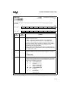
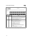
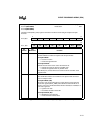
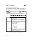
The control registers for the timers are T1CONTROL (Figure 11-8) and T2CONTROL (Figure
11-9). Write to these registers to configure the timers. Write to the TIMER1 and TIMER2 regis-
ters (see Table 11-3 on page 11-3 for addresses) to load a specific timer value.


