8XC196MC, MD, MH USER’S MANUAL
5-46
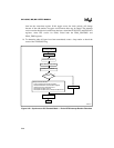
time into the event-time register. If this toggle occurs, the clock polarity will change
because of the odd number of toggles and erroneous data may be output. The interrupt
service routine should also load the next data byte, reload the PTSCOUNT and PTSCON1
registers, select PTS service for EPA0, reload both the EPA0_CONTROL and
EPA0_TIME registers.
14. To determine when all bytes have been transmitted, create a loop routine to check the
status of the TXDDONE flag.
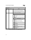
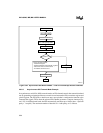
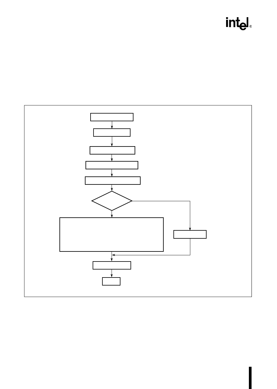
Figure 5-22. Synchronous SIO Transmit Mode — End-of-PTS Interrupt Routine Flowchart
A3274-01
End-Of-PTS Interrupt
Save Critical Data
Set-up next data transfer
- Load next data byte into DATA register
- Reload PTSCOUNT and PTSCON1 registers
- Select PTS service for EPA channel
- Re-initialize the EPA channel
- Re-initialize the EPA timer to initiate first bit transfer
Load Critical Data
Return
TXDDONE = 1
T_COUNT = T_COUNT - 1
Y
N
T_COUNT = 0?
Clear Interrupt Request Bit
Disable EPA Channel


