8XC196MC, MD, MH USER’S MANUAL
12-8
12.4.5 Enabling the A/D Interrupt
The A/D converter can set the A/D interrupt pending bit when it completes a conversion or when
the input voltage crosses the threshold value in the selected direction. To enable the interrupt, set
the corresponding mask bit in the interrupt mask register (see Table 12-2 on page 12-2) and exe-
cute the EI instruction to globally enable servicing of interrupts. The A/D interrupt can cause the
PTS to begin a new conversion. See Chapter 5, “Standard and PTS Interrupts,” for details about
interrupts and a description of using the PTS in A/D scan mode.
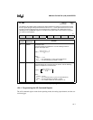
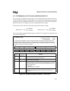
AD_COMMAND
Address:
Reset State:
1FACH
80H
The A/D command (AD_COMMAND) register selects the A/D channel number to be converted,
controls whether the A/D converter starts immediately or with an EPA command, and selects the
conversion mode.
7 0
— M1 M0 GO ACH3 ACH2 ACH1 ACH0
Bit
Number
Bit
Mnemonic
Function
7 — Reserved; for compatibility with future devices, write zeros to these bits.
6:5 M1:0 A/D Mode†
These bits determine the A/D mode.
M1 M0 Mode
0 0 10-bit conversion
0 1 8-bit conversion
1 0 threshold detect high
1 1 threshold detect low
4 GO A/D Conversion Trigger††
Writing this bit arms the A/D converter. The value that you write to it
determines at what point a conversion is to start.
0 = EPA initiates conversion
1 = start immediately
3:0 ACH3:0 A/D Channel Selection
Write the A/D conversion channel number to these bits.
†
While a threshold-detection mode is selected for an analog input pin, no other conversion can be
started. If another value is loaded into AD_COMMAND, the threshold-detection mode is disabled
and the new command is executed.
††
It is the act of writing to the GO bit, rather than its value, that starts a conversion. Even if the GO bit
has the desired value, you must set it again to start a conversion immediately or clear it again to
arm it for an EPA-initiated conversion.
Figure 12-5. A/D Command (AD_COMMAND) Register


