5-25
STANDARD AND PTS INTERRUPTS
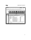
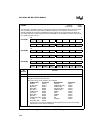
The address of the first (lowest) PTSCB byte is stored in the PTS vector table in special-purpose
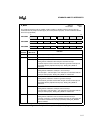
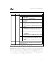
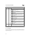
memory (see “Special-purpose Memory” on page 4-3). Figure 5-13 shows the PTSCB for each
PTS mode. Unused PTSCB bytes can be used as extra RAM.
NOTE
The PTSCB must be located in the internal register file. The location of the
first byte of the PTSCB must be aligned on a quad-word boundary (an address
evenly divisible by 8).
5.6.1 Specifying the PTS Count
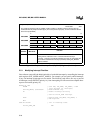
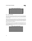
The first location of the PTSCB contains an 8-bit value called PTSCOUNT. This value defines
the number of interrupts that will be serviced by the PTS routine. The PTS decrements
PTSCOUNT after each PTS cycle. When PTSCOUNT reaches zero, hardware clears the corre-
sponding PTSSEL bit and sets the PTSSRV bit (Figure 5-6), which requests an end-of-PTS inter-
rupt. The end-of-PTS interrupt service routine should reinitialize the PTSCB, if required, and set
the appropriate PTSSEL bit to re-enable PTS interrupt service.
Single
Transfer
Block
Transfer
A/D Scan
Mode
SIO #1
†
SIO #2
†
Unused Unused Unused PTSVEC1 (H) Unused
Unused PTSBLOCK Unused PTSVEC1 (L) SAMPTIME
PTSDST(H) PTSDST (H) PTSPTR2 (H) BAUD (H) DATA (H)
PTSDST (L) PTSDST (L) PTSPTR2 (L) BAUD (L) DATA (L)
PTSSRC (H) PTSSRC (H) PTSPTR1 (H) EPAREG (H) PTSCON1
PTSSRC (L) PTSSRC (L) PTSPTR1 (L) EPAREG (L) PORTMASK
PTSCON PTSCON PTSCON PTSCON PORTREG (H)
PTSVECT PTSCOUNT PTSCOUNT PTSCOUNT PTSCOUNT PORTREG (L)
†
8XC196MC and MD only.
Figure 5-13. PTS Control Blocks


