SECTION 7—BACK ADJUSTMENTS
Part No 1114842 81 2G Tarsys®Powered Seating System
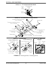
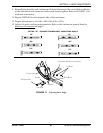
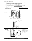
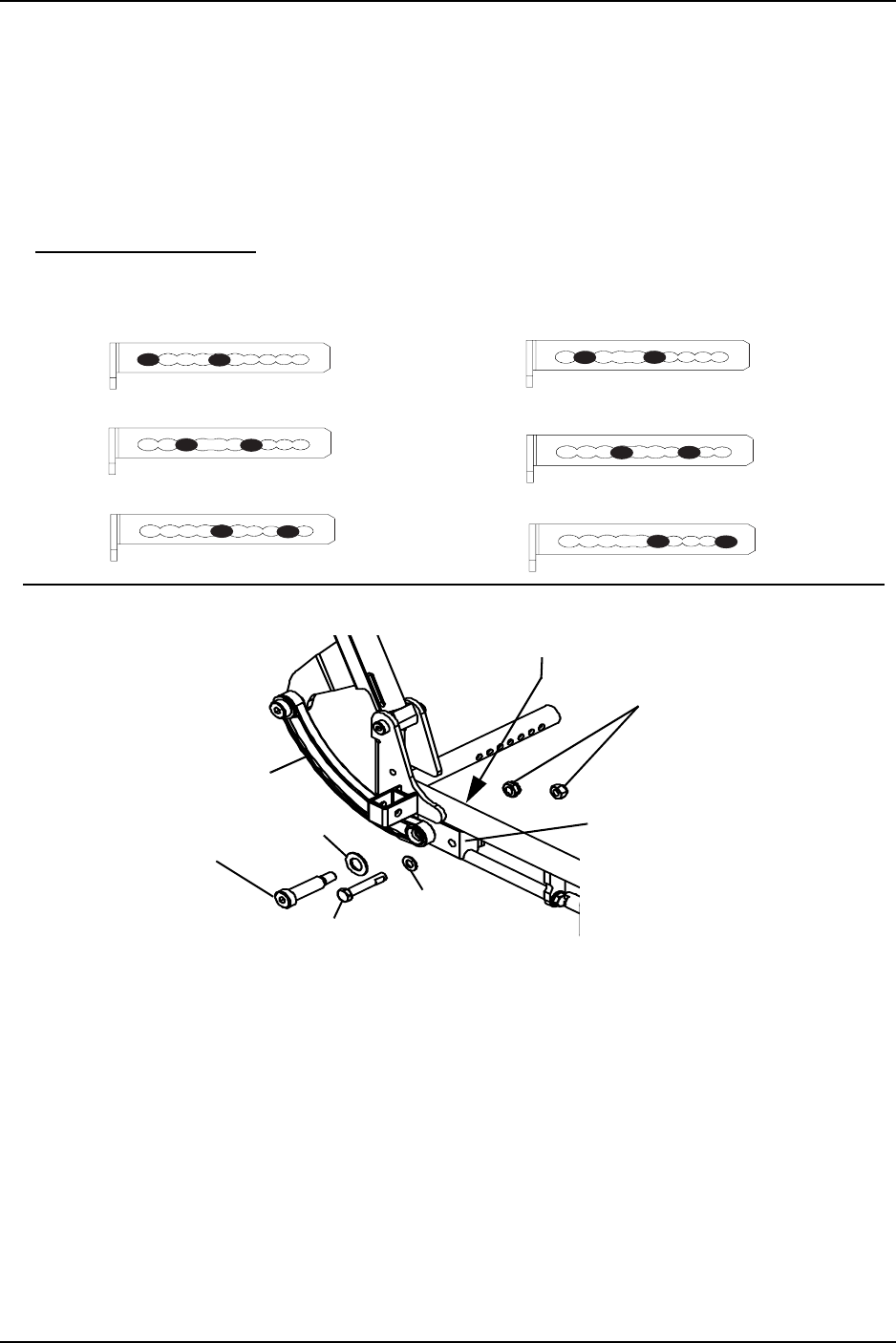
9. Reinstall the shoulder bolt, washer and locknut that secure the curved link to the rear
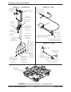
of the slide block and connector bracket and loosely tighten. Refer to FIGURE 7.1 for
hardware orientation.
10. Repeat STEPS 8-9 for the opposite side of the seat frame.
11. Torque all locknuts to 13 ft-lbs ± 20% (156 in-lbs ± 20%).
12. Adjust tilt and/or recline potentiometers. Refer to the electronics manual listed in
Reference Documents on page 2.
FIGURE 7.1 Adjusting Back Angle
Connector Bracket (not shown)
Locknuts
Slide Block
Washer
Hex Bolt
Shoulder Bolt
Washer
Curved Link
90°
100°
110°
95°
105°
115°
DETAIL “A” - CONNECTOR BRACKET MOUNTING HOLES


