


SECTION 14—ELECTRONICS
Part No 1114842 143 2G Tarsys®Powered Seating System
8. Slide the controller bracket up/down on the back cane until the bottom of the
controller bracket is 1-inch ± ¼-inch above the top of the pivot arm (Detail “A”
FIGURE 14.3 on page 145).
9. Torque the hex screws to 75 in-lbs ± 20% to secure the controller bracket to the T-nuts
and back cane.
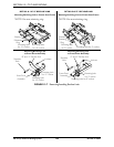
10. Align the T-nuts on the spreader bar with the slots in the back canes.
11. Slide the spreader bar to the position noted when removing the spreader bar (Detail
“A” of FIGURE 14.2).
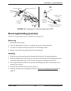
12. Make sure the measurements shown in Detail “B” of FIGURE 14.2 and noted in STEP
2 are the same on both sides.
13. Tighten the four hex screws that secure the spreader bar to the back canes. Torque to
75 in-lbs ± 20%.
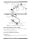
14. Program the TAC. Refer to Programming the TAC on page 146.
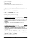
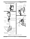
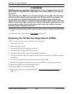
FIGURE 14.2 Controller Bracket
Hex
Screws/T-Nuts
(T-Nuts in Back
Cane Slot)
Spreader Bar
DETAIL “B”
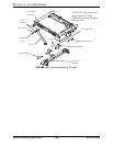
VSR Actuator
Locknut
Hex Bolt
Back Pan ASM
NOTE A: Measurements from
the top of the back cane to the top
of the back pan MUST be equal.
NOTE B: Measurements from
the top of the back cane to the top
of the spreader bar MUST be
equal.
NOTE A
NOTE B
DETAIL “A”