


SECTION 6—SEAT ADJUSTMENTS
2G Tarsys®Powered Seating System 78 Part No 1114842
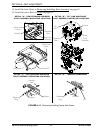
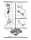
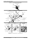
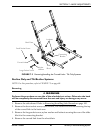
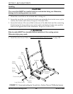
FIGURE 6.18 Removing the Seat - Connecting the Seat
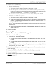
DETAIL “A” - TILT POTENTIOMETER LINKAGE
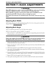
DETAIL “B” - TILT LINKS AND TILT ANGLE BLOCKS
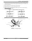
DETAIL “C” - RECLINE LINKS
DETAIL “D” - REAR PIVOT
ASSEMBLY
Socket
Screw
Tilt Potentiometer
Linkage
Center
Seat
Frame
Orientation of angle block shown
is for 5° seat angle
Locknuts
Spacer
Spacer
Link
Shoulder Bolt
Mounting Hole for 0°
seat angle
Use this mounting hole for
0° seat angle
Front Pivot Assembly
Orientation of angle block shown
is for 0° seat angle
Shoulder Bolt
Link
Mounting Hole for 5°
Seat Angle
Use this mounting
hole for 5° seat angle
10° and 15°
Recline Link
Shoulder
Bolt
Front Pivot
Assembly
Locknut
Mounting hole
for 10° recline
Mounting
hole for 15°
recline
Mounting
hole for 5°
recline
Mounting hole for
0° recline
Front Pivot
Assembly
Locknut
0° and 5° Recline Link
Shoulder Bolt
0° and 5° Recline Link
10° and 15° Recline Link
Locknut
Center
Seat
Frame
Shoulder
Bolt
Rear Pivot Assembly