


SECTION 5—INTERFACE HARDWARE
Part No 1114842 25 2G Tarsys®Powered Seating System
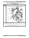
NOTE: Not all mounting positions require the front pivot assembly to be secured to the lower
interface brackets. Some mounting positions require that the front pivot assembly be secured to the
seat brackets only. The hex screws securing the front pivot assembly to the seat brackets DO NOT
need to be removed.
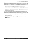
5. Adjust the position of the seating system on the lower interface brackets.
6. Using the two hex screws and locknuts removed in STEP 3, secure the insides of the
seat brackets to the lower interface brackets. Torque to 13 ft-lbs ± 20%.
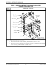
7. Using the hex screws and locknuts removed in STEP 4, secure the front pivot assembly
to the front of the seat brackets and the front of the seat brackets to the lower interface
brackets. Torque to 13 ft-lbs ± 20%.
NOTE: Not all mounting positions require the front pivot assembly to be secured to the lower
interface brackets. Some mounting positions require that the front pivot assembly be secured to the
seat brackets only.
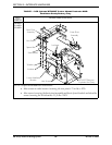
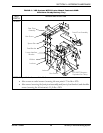
8. Using the six hex screws, washers and locknuts removed in STEP 2, secure the rear
pivot assembly and the spacer bars to the seat brackets and lower interface brackets.
Torque to 75 in-lbs ± 20%.
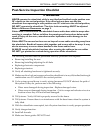
9. Perform the post-service inspection checklist. Refer to Post-Service Inspection
Checklist on page 21.