


SECTION 5—INTERFACE HARDWARE
Part No 1114842 47 2G Tarsys®Powered Seating System
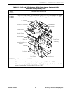
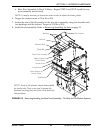
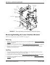
7. Remove the two socket screws, washers and locknuts securing the front of the lower
portion of the linear guides to the seat bracket.
8. Slide the rear pivot assembly backward.
9. Align the rear access holes with the rear two socket screws securing the upper portion
of the linear guides and clamp bars to the rear pivot assembly.
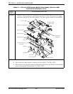
10. Remove the two socket screws securing the upper portion of the linear guides and
clamp bars to the rear pivot assembly.
11. Slide the rear pivot assembly forward.
12. Align the access holes revealed after performing STEP 6 with the front two socket
screws securing the upper portion of the linear guides and clamp bars to the rear pivot
assembly.
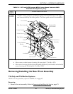
13. Repeat STEP 10 and STEP 11 for the remaining two socket screws securing the upper
portion of the linear guides and clamp bars to the rear pivot assembly.
NOTE: Retain the clamp bars for reinstallation.
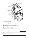
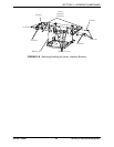
Installing
1. Reverse STEP 8 to STEP 13 in Removing to install the rear pivot onto the linear guides.
Torque socket screws to 75 in-lbs ± 20%.
2. Reverse STEP 3 to STEP 7 in Removing to install the linear guides onto the seat
bracket. Hand tighten the two socket screws securing the linear guides to the seat
brackets.
CAUTION
The linear guides MUST be parallel and the rear pivot assembly MUST move freely
on the linear guides. Otherwise, damage to the seating system will occur during
operation.
3. Adjust the linear guides until they are parallel.
4. Slide the rear pivot assembly forward and back to see if it slides freely on the linear
guides.
5. Perform one of the following:
• Rear Pivot Assembly Slides Freely - Proceed to STEP 6.
• Rear Pivot Assembly Is Hard To Move - Repeat STEP 3 and STEP 4 until the rear
pivot assembly moves freely.
NOTE: It may be necessary to loosen the socket screws to adjust the linear guides.
6. Torque the socket screws to 75 in-lbs ± 20%.
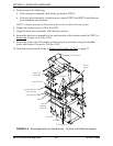
7. Secure the rear of the tilt actuator to the rear pivot assembly using the shoulder bolt,
two bushings and the locknut. Torque to 23 ft-lbs ± 20%.
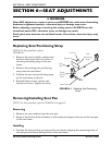
8. Install the seat assembly. Refer to Removing/Installing the Seat
on page 75.