


SECTION 14—ELECTRONICS
2G Tarsys®Powered Seating System 140 Part No 1114842
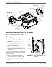
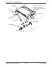
6. Disconnect the auxiliary power connector of the SAC from the power take off
connector of the MK
5
controller.
7. Disconnect the tilt potentiometer connector from the SAC 3-pin Molex connector.
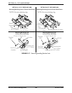
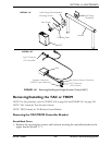
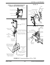
8. Remove the two hex screws securing the half clamps to the armrest. Refer to
Detail “A”.
9. Remove the SAC and mounting hardware from the armrest.
NOTE: The mounting hardware includes the half clamps, mounting plate, hex screws and
mounting screws.
10. Remove the two mounting screws securing the SAC to the mounting plate.
11. Remove the SAC from the mounting plate.
Installing
1. Secure the SAC to the mounting plate using the two mounting screws.
2. If necessary, secure the mounting plate to the non-threaded half clamp using the two
hex screws.
3. Position the non-threaded half clamp onto the armrest.
4. Secure the threaded half clamp to the armrest by tightening the two hex screws.
5. Connect the SAC 5-pin connector to the MK
5
controller (at the rear of the battery box).
6. Connect the SAC actuator connector (WHITE, 2-pin Anderson) to the tilt actuator
cable.
7. Connect the auxiliary power connectors.
8. Connect the tilt potentiometer connector to the SAC 3-pin Molex connector.
9. Secure the SAC cables. Refer to Securing the Cables on page 157.
10. Adjust the tilt potentiometer. Refer to Adjusting the Tilt Potentiometer
on page 152.
11. Perform the post-service inspection. Refer to Post-Service Inspection Checklist on
page 21.
12. Install the rear shroud. Refer to Removing/Installing Rear Shroud on page 102.