


SECTION 11—CENTER MOUNT FOOTRESTS
2G Tarsys®Powered Seating System 122 Part No 1114842
Before 2/15/07
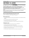
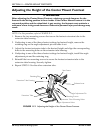
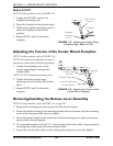
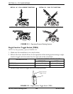
NOTE: For this procedure, refer to FIGURE 11.5.
1. Loosen, but DO NOT remove, the
footplate mounting screw.
2. Move the footplate to the desired angle.
3. Tighten the footplate mounting screw to
secure the footplate in the desired
position.
4. Repeat STEPS 1 and 2 for the other
footplate.
FIGURE 11.5 Adjusting the Center Mount
Footplate Angle - Before 2/15/07
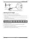
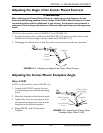
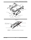
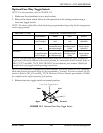
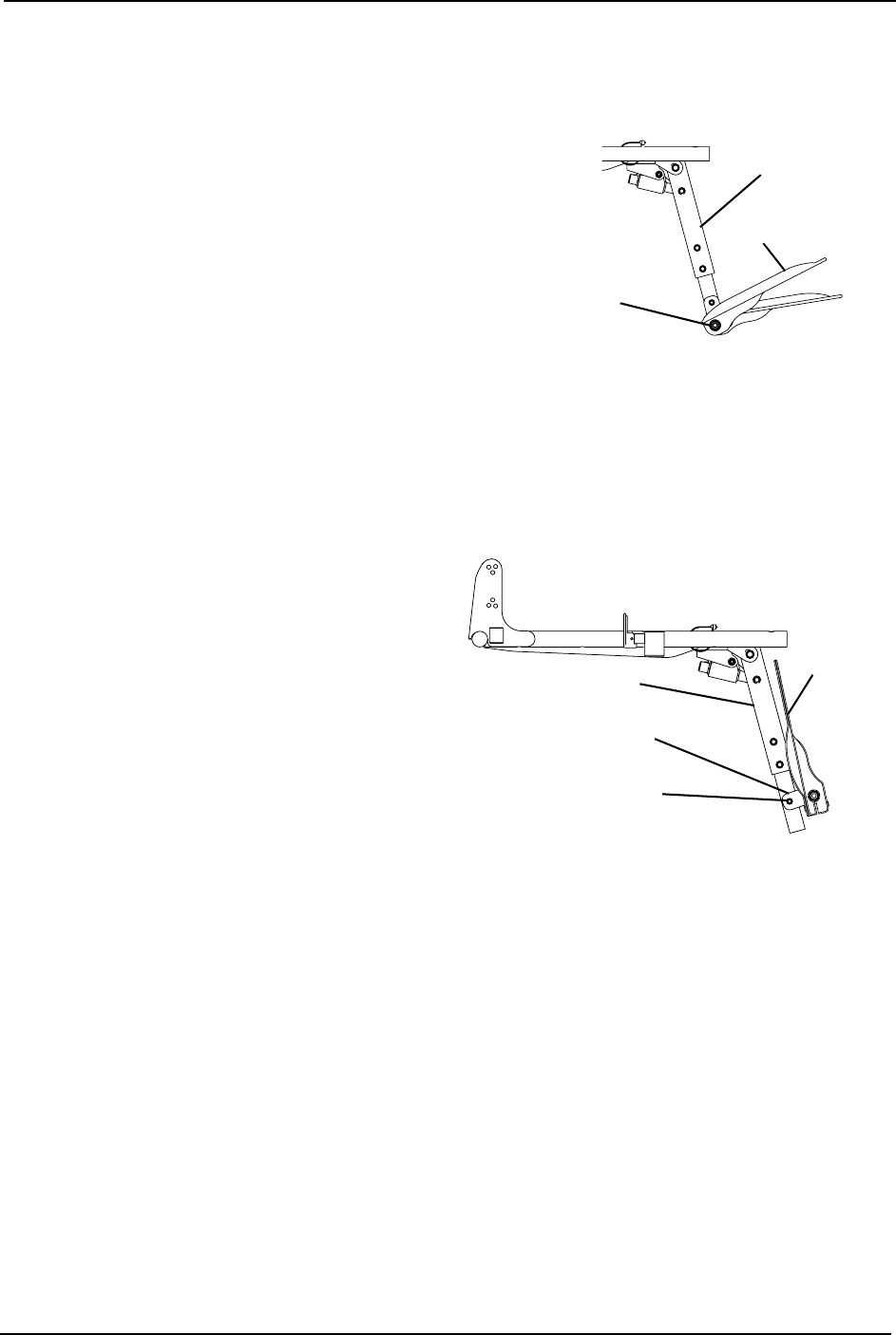
Adjusting the Tension of the Center Mount Footplate
NOTE: For this procedure, refer to FIGURE 11.6.
NOTE: The tension can be adjusted to increase or
decrease the rotation effort of the flip up footplates.
1. Loosen the mounting screw on the
footrest angle hinge to decrease the
rotation effort.
NOTE: DO NOT remove the mounting screw.
2. Tighten the footrest angle hinge
mounting screw to increase the rotation
effort.
3. Repeat STEPS 1 and 2 for the other
footplate.
FIGURE 11.6 Adjusting the Tension of the
Center Mount Footplate
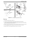
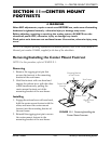
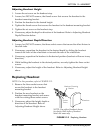
Removing/Installing the Release Lever Assembly
NOTE: For this procedure, refer to FIGURE 11.7 on page 123.
1. Remove the mounting screw that secures the side shroud in place.
2. Secure the ratchet housing to the mounting bracket on the seat frame with the mounting
screw and locknut provided. Securely tighten.
3. Secure the release handle to the seat frame with the mounting screw, spacer and square
nut provided. Securely tighten.
4. Tie-wrap cable as shown in Detail “A”. Leave enough slack in the cable to loop around the
mounting screw that secures the side shroud in place.
5. Secure the side shroud in place with existing mounting screw. Securely tighten.
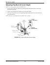
Center Mount
Footrest
Footplate
Footplate
Mounting
Screw
Footplate
Footrest Angle Hinge
Mounting Screw
Footrest Angle Hinge
Center Mount
Footrest