


Interrupt Control Unit
8-11
8.2.2 Cascade Mode
The Am186ER and Am188ER microcontrollers have five interrupt pins, two of which (INT2
and INT3) have dual functions. In fully nested mode, the five pins are used as direct interrupt
inputs and the corresponding interrupt types are generated internally. In Cascade mode,
four of the five pins can be configured into interrupt input and dedicated acknowledge signal
pairs. INT0 can be configured with interrupt acknowledge INTA
0 (INT2). INT1 can be
configured with interrupt acknowledge INTA
1 (INT3).
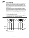
External sources in Cascade mode use externally generated interrupt types. When an
interrupt is acknowledged, two INTA
cycles are initiated and the type is read into the
microcontroller on the second cycle (see section 8.1.5 on page 8-8). The capability to interface
to one or two external 82C59A programmable interrupt controllers is provided when the inputs
are configured in Cascade mode.
When INT0 is the only pin configured in Cascade mode, it must be programmed to a higher
priority than INT1. When INT1 is the only pin configured in Cascade mode, it must be
programmed to a higher priority than any other maskable interrupt.
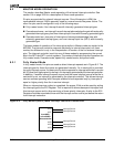
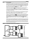
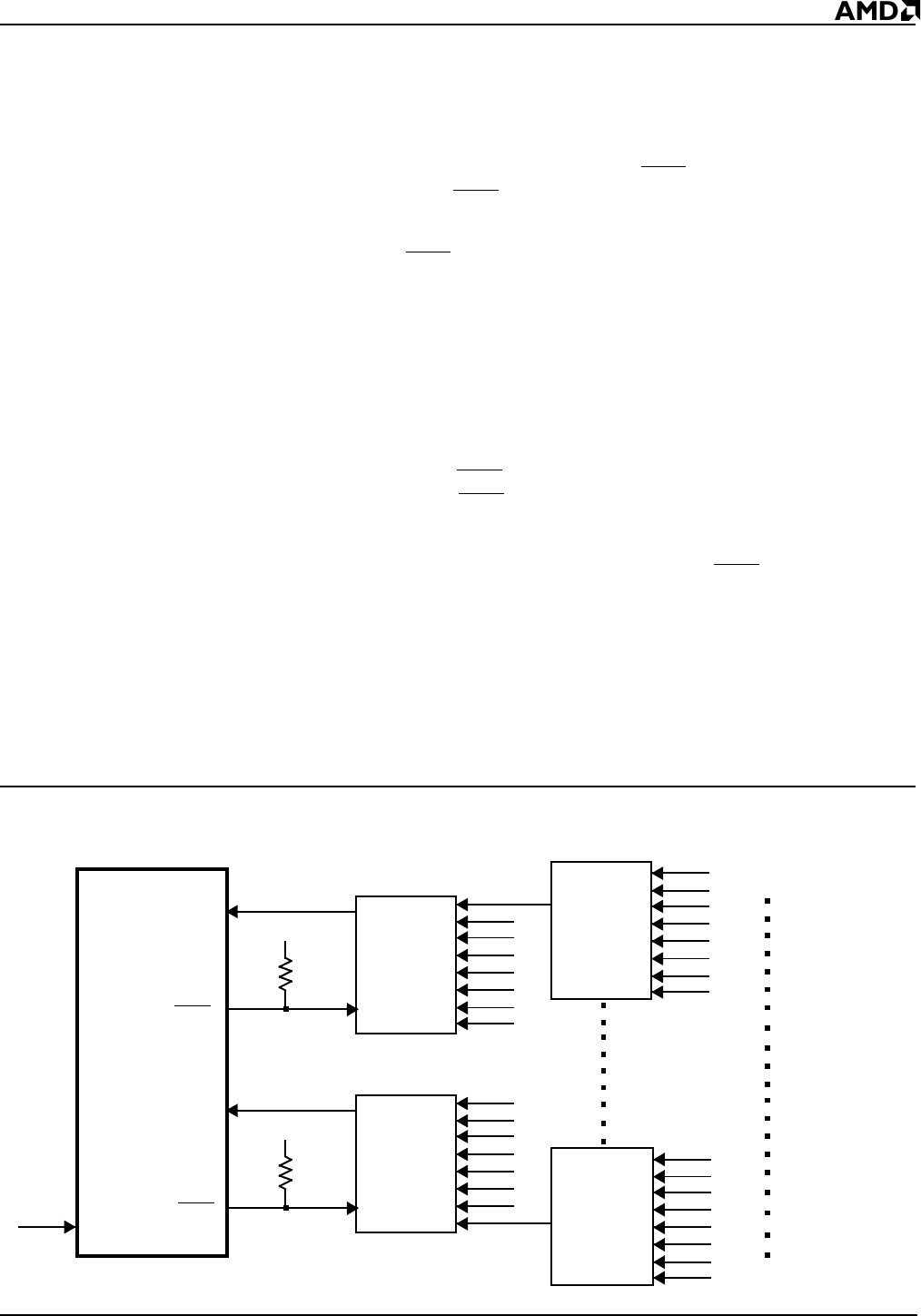
Figure 8-3 shows the interconnection for Cascade mode. INT0 is an interrupt input
interfaced to one 82C59A, and INT2/INTA
0 serves as the dedicated interrupt acknowledge
signal to that peripheral. INT1 and INT3/INTA
1 are also interfaced to an 82C59A. Each interrupt
and acknowledge pair can be selectively placed in the cascade or non-Cascade mode by
programming the proper value into the INT0 and INT1 control registers. The dedicated
acknowledge signals eliminate the need for external logic to generate INTA
and device select
signals.
Cascade mode provides the capability to serve up to 128 external interrupt sources through
the use of external master and slave 82C59As. Three levels of priority are created, requiring
priority resolution in the microcontroller interrupt controller, the master 82C59As, and the
slave 82C59As. If an external interrupt is serviced, one IS bit is set at each of these levels.
When the interrupt service routine is completed, up to three End-Of-Interrupt (EOI) Register
writes must be issued by the program.
Figure 8-3 Cascade Mode Interrupt Controller Connections
Am186ER
or Am188ER
Microcontroller
82C59A
INT0
V
CC
82C59A
V
CC
INT1
82C59A
82C59A
Interrupt Sources
Interrupt Sources
INTA0
INTA
1
INT4