


Programmable I/O Pins
13-3
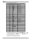
13.2 PIO MODE REGISTERS
Table 13-2 shows the possible settings for the PIO Mode and PIO Direction bits. The
Am186ER and Am188ER microcontrollers default the 32 PIO pins to either 00b (normal
operation) or 01b (PIO input with weak internal pullup or pulldown enabled).
Pins that default to active High outputs at reset are pulled down. All other pins are pulled
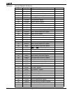
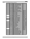
up or are normal operation. See Table 13-2. The column titled
Power-On Reset Status
in
Table 13-1 lists the defaults for the PIOs.
The internal pullup resistor has a value of approximately 100 kohms. The internal pulldown
resistor has a value of approximately 100 kohms.
Table 13-2 PIO Mode and PIO Direction Settings
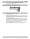
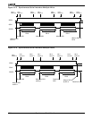
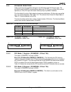
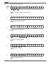
13.2.1 PIO Mode 1 Register (PIOMODE1, Offset 76h)
The value of PIOMODE1 at reset is 0000h.
Bits 15–0: PIO Mode Bits (PMODE31–PMODE16)—This field with the PIO direction
registers determines whether each PIO pin performs its pre-assigned function or is enabled
as a custom PIO signal. The most significant bit of the PMODE field determines whether
PIO31 is enabled, the next bit determines whether PIO30 is enabled, and so on.
Table 13-2 shows the values that the PIO mode bits and the PIO direction bits can encode.
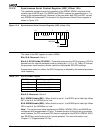
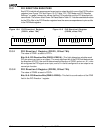
13.2.2 PIO Mode 0 Register (PIOMODE0, Offset 70h)
The value of PIOMODE0 at reset is 0000h.
Bits 15–0: PIO Mode Bits (PMODE15–PMODE0)—This field is a continuation of the
PMODE field in the PIO Mode 1 register.
PIO Mode PIO Direction Pin Function
0 0 Normal operation
0 1 PIO input with pullup/pulldown
1 0 PIO output
1 1 PIO input without pullup/pulldown
15 7 0
PMODE (31–16)
15 7 0
PMODE (15–0)
Figure 13-3 PIO Mode 0 Register
(PIOMODE0, offset 70h)
Figure 13-2 PIO Mode 1 Register
(PIOMODE1, offset 76h)