


Chip Select Unit
5-11
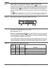
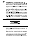
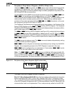
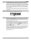
Bit 7: Pin Selector (EX)—This bit determines whether the PCS6–PCS5 pins are configured
as chip selects or as alternate outputs for A2–A1. When this bit is set to 1, PCS
6–PCS5
are configured as peripheral chip select pins. When EX is set to 0, PCS
5 becomes address
bit A1 and PCS
6 becomes address bit A2.
Bit 6: Memory/ I/O Space Selector (MS)—This bit determines whether the PCS
pins are
active during memory bus cycles or I/O bus cycles. When MS is set to 1, the PCS
outputs
are active for memory bus cycles. When MS is set to 0, the PCS
outputs are active for I/O
bus cycles.
Bits 5–3: Reserved—Set to 1.
Bit 2: Ready Mode (R2)—This bit applies only to the PCS
6–PCS5 chip selects. If R2 is
set to 0, external ready is required. If R2 is set to 1, external ready is ignored. In each case,
the processor also uses the value of the R1–R0 bits to determine the number of wait states
to insert.
Bits 1–0: Wait-State Value (R1–R0)—These bits apply only to the PCS
6–PCS5 chip
selects. The value of R1–R0 determines the number of wait states inserted into an access
to the PCS
memory or I/O area. From zero to three wait states can be inserted
(R1–R0 = 00b to 11b).