


Interrupt Control Unit
8-1
CHAPTER
8
INTERRUPT CONTROL UNIT
8.1 OVERVIEW
The Am186ER and Am188ER microcontrollers can receive interrupt requests from a variety
of sources, both internal and external. The internal interrupt controller arranges these
requests by priority and presents them one at a time to the CPU.
There are six external interrupt sources on the Am186ER and Am188ER microcontrollers—
five maskable interrupt pins (INT4–INT0) and the nonmaskable interrupt (NMI) pin. There
are six internal interrupt sources that are not connected to external pins—three timers, two
DMA channels, and the asynchronous serial port.
The Am186ER and Am188ER microcontrollers provide three interrupts that are not present
on the 80C186 and 80C188 microcontrollers:
n INT4, an additional external interrupt pin that operates like the INT3–INT0 pins
n An internal watchdog timer interrupt
n An internal interrupt from the serial port
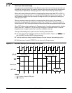
The INT4–INT0 interrupt request pins can be used as direct interrupt requests, and can be
either edge triggered or level triggered. If more inputs are needed, INT1 and INT0 can be
configured in Cascade mode for use with an 82C59A-compatible external interrupt
controller, using INT2/INTA
0 and INT3/INTA1 for the corresponding interrupt acknowledge
signals. An external interrupt controller can be used as the system master by programming
the internal interrupt controller to operate in Slave mode. In all cases, nesting can be enabled
that allows high priority interrupts to interrupt lower-priority interrupt service routines.
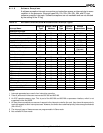
8.1.1 Definitions of Interrupt Terms
The following definitions cover some of the terminology that is used in describing the
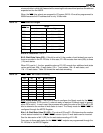
functionality of the interrupt controller. Table 8-1 contains information regarding the
reserved interrupts.
8.1.1.1 Interrupt Type
An 8-bit interrupt type identifies each of the 256 possible interrupts.
Software exceptions, internal peripherals, and non-cascaded external interrupts supply the
interrupt type through the internal interrupt controller.
Cascaded external interrupts and slave-mode external interrupts get the interrupt type from
the external interrupt controller by means of interrupt acknowledge cycles on the bus.
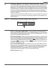
8.1.1.2 Interrupt Vector Table
The interrupt vector table is a memory area of 1 Kbyte beginning at address 00000h that
holds up to 256 four-byte address pointers containing the address for the interrupt service
routine for each possible interrupt type. For each interrupt, an 8-bit interrupt type identifies
the appropriate interrupt vector table entry.
Interrupts 00h to 1Fh are reserved. See Table 8-1.