


Timer Control Unit
9-2
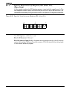
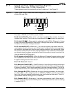
Each timer also has a corresponding maximum-count register that defines the maximum
value for the timer. When the timer reaches the maximum value, it resets to 0 during the
same clock cycle. (The value in the timer-count register never equals the maximum-count
register.) In addition, timers 0 and 1 have a secondary maximum-count register. Using both
the primary and secondary maximum-count registers lets the timer alternate between two
maximum values.
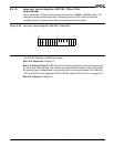
If the timer is programmed to use only the primary maximum-count register, the timer output
pin switches Low for one clock cycle, the clock cycle after the maximum value is reached.
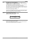
If the timer is programmed to use both of its maximum-count registers, the output pin creates
a waveform by indicating which maximum-count register is currently in control. The duty
cycle and frequency of the waveform depend on the values in the alternating maximum-
count registers. For example, a 50% duty cycle waveform can be generated at 1/8 the
frequency of the system clock using a 1h value for maxcount A and maxcount B.
9.2.1 Timer Operating Frequency
Each timer is serviced on every fourth clock cycle. Therefore, a timer can operate at a
maximum speed of one-quarter of the internal clock frequency. A timer can be clocked
externally at the same maximum frequency of one-fourth of the internal clock frequency.
However, because of internal synchronization and pipelining of the timer circuitry, the timer
output takes up to six clock cycles to respond to the clock or gate input.
The timers are run by the processor’s internal clock. If power-save mode is in effect, the
timers operate at the reduced power-save clock rate.