


Interrupt Control Unit
8-22
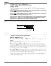
8.3.8 Interrupt Request Register (REQST, Offset 2Eh)
(Master Mode)
The hardware interrupt sources have interrupt request bits inside the interrupt controller.
A read from this register yields the status of these bits. The Interrupt Request (REQST)
Register is a read-only register. The format of the Interrupt Request Register is shown in
Figure 8-11.
For internal interrupts (watchdog, DMA, serial port, or timer interrupts) the corresponding
interrupt request bit (WD, D1, D0, TMR, or SPI) is set to 1 when the device requests an
interrupt.
Once set, interrupt request bit WD, D1, or D0 is reset during the internally generated interrupt
acknowledge. Bit TMR remains set as long as INTSTS Register bit TMR2, TMR1, or TMR0
is set. Bit SPI remains set until the serial port condition that caused the interrupt is cleared.
For INT4–INT0 external interrupts, the corresponding bit (I4–I0) reflects the current value
of the external signal. The device must hold this signal High until the interrupt is serviced.
Generally the interrupt service routine signals the external device to remove the interrupt
request.
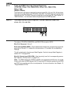
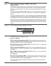
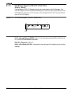
Figure 8-11 Interrupt Request Register (REQST, offset 2Eh)
The REQST Register is undefined on reset.
Bits 15–11: Reserved
Bit 10: Serial Port Interrupt Request (SPI)—This bit indicates the interrupt state of the
serial port. If enabled, the SPI bit is the logical OR of all possible serial port interrupt sources
(THRE, RDR, BRKI, FER, PER, and OER status bits).
Bit 9: Watchdog Timer Interrupt Request (WD)—When this bit is set to 1, the Watchdog
Timer has an interrupt pending.
Bits 8–4: Interrupt Requests (I4–I0)—When set to 1, the corresponding INT pin has an
interrupt pending (i.e., when INT0 is pending, I0 is set). These bits reflect the status of the
external pin.
Bits 3–2: DMA Channel Interrupt Request (D1–D0)—When set to 1, the corresponding
DMA channel has an interrupt pending.
Bit 1: Reserved
Bit 0: Timer Interrupt Request (TMR)—This bit indicates the state of the timer interrupts.
This bit is the logical OR of the timer interrupt requests. When set to a 1, this bit indicates
that the timer control unit has an interrupt pending.
The Interrupt Status Register indicates the specific timer that is requesting an interrupt.
See section 8.3.7.
15
70
Reserved
Res
TMRD0
D1
I0
I1
I2
I3
I4
WD
SPI