


Synchronous Serial Interface
12-3
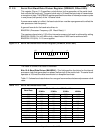
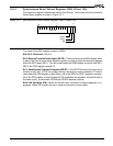
12.2.1 Synchronous Serial Status Register (SSS, Offset 10h)
This read-only register indicates the state of the SSI port. The format of the Synchronous
Serial Status register is shown in Figure 12-1.
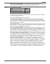
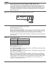
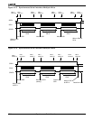
Figure 12-1 Synchronous Serial Status Register (SSS, offset 10h)
The value of the SSS register at reset is 0000h.
Bits 15–3: Reserved—Set to 0.
Bit 2: Receive/Transmit Error Detect (RE/TE)—This bit is set when the SSI detects either
a read of the Synchronous Serial Receive register or a write to one of the transmit registers
while the SSI is busy (PB=1). This bit is reset when the SDEN output is inactive (bits DE1–
DE0 in the SSC register are both 0).
Bit 1: Data Receive/Transmit Complete (DR/DT)—The DR/DT bit is set at the end of the
transfer of data bit 7 (SCLK rising edge) during a transmit or receive operation. This bit is
reset when the SSR register is read, when one of the SSD0 or SSD1 registers is written,
when the SSS register is read (unless the SSI completes an operation and sets the bit in
the same cycle), or when both SDEN0 and SDEN1 become inactive.
Bit 0: SSI Port Busy (PB)—When the PB bit is set, a transmit or receive operation is in
progress. When PB is reset, the port is ready to transmit or receive data.
15
70
Reserved
RE/TE
DR/DT
PB