


DMA Controller
10-4
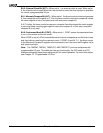
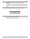
Bit 11: Source Decrement (SDEC)—When SDEC is set to 1, the source address is
automatically decremented after each transfer. The address decrements by 1 or 2
depending on the byte/word bit (B
/W, bit 0). The address remains constant if the increment
and decrement bits are set to the same value (00b or 11b).
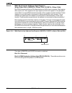
Bit 10: Source Increment (SINC)—When SINC is set to 1, the source address is
automatically incremented after each transfer. The address increments by 1 or 2 depending
on the byte/word bit (B
/W, bit 0). The address remains constant if the increment and
decrement bits are set to the same value (00b or 11b).
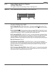
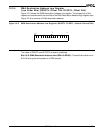
Bit 9: Terminal Count (TC)—The DMA decrements the transfer count for each DMA
transfer. When TC is set to 1, source or destination synchronized DMA transfers terminate
when the count reaches 0. When TC is set to 0, source or destination synchronized DMA
transfers do not terminate when the count reaches 0. Unsynchronized DMA transfers
always terminate when the count reaches 0, regardless of the setting of this bit.
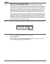
Bit 8: Interrupt (INT)—When INT is set to 1, the DMA channel generates an interrupt
request on completion of the transfer count. The TC bit must also be set to generate an
interrupt.
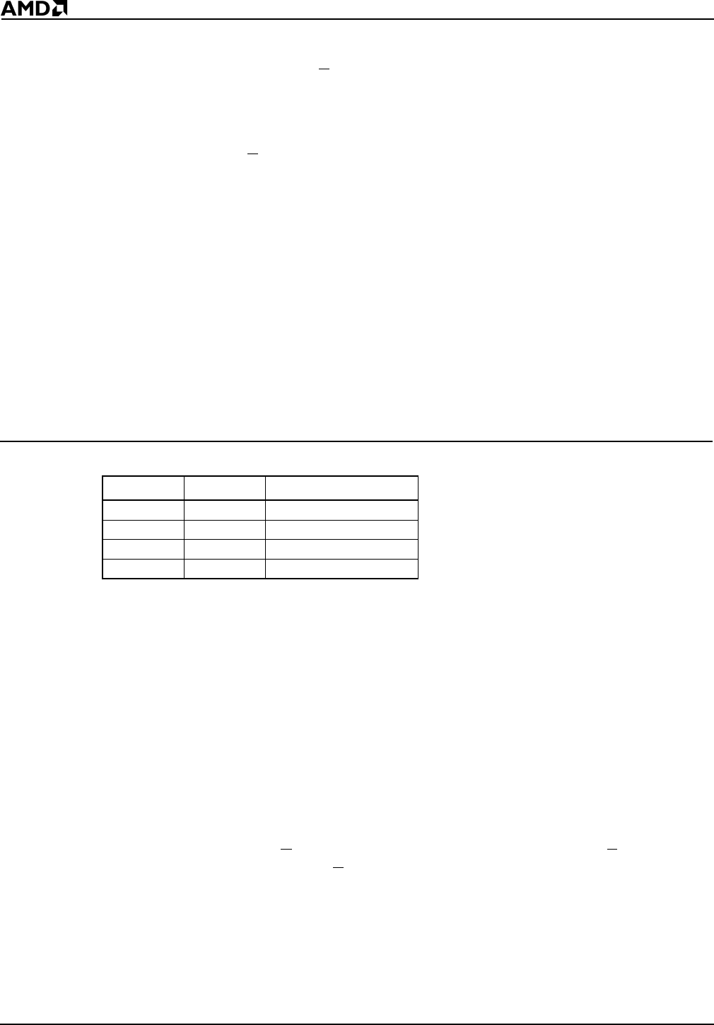
Bits 7–6: Synchronization Type (SYN1–SYN0)—The SYN1–SYN0 bits select channel
synchronization as shown in Table 10-2. For more information on DMA synchronization,
see section 10.4 on page 10-10.
Table 10-2 Synchronization Type
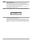
Bit 5: Relative Priority (P)—When P is set to 1, it selects high priority for this channel
relative to the other channel during simultaneous transfers.
Bit 4: Timer Enable/Disable Request (TDRQ)—When TDRQ is set to 1, it enables DMA
requests from timer 2. When set to 0, TDRQ disables DMA requests from timer 2.
Bit 3: Reserved
Bit 2: Change Start Bit (CHG)—This bit must be set to 1 during a write to allow modification
of the ST bit. When CHG is set to 0 during a write, ST is not altered when writing the control
word.
Bit 1: Start/Stop DMA Channel (ST)—The DMA channel is started when the start bit is
set to 1. This bit can be modified only when the CHG bit is set to a 1 during the same
register write.
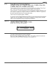
Bit 0: Byte/Word Select (B
/W)—On the Am186ER microcontroller, when B/W is set to 1,
word transfers are selected. When B
/W is set to 0, byte transfers are selected. The Am186ER
does not support word DMA transfers to or from memory configured for 8-bit accesses. Word
transfers are not supported on the Am188ER microcontroller.
Note: The DMA request pins DRQ0 and DRQ1 are multiplexed with programmable I/O
pins. To enable the pins to function as DMA requests, the PIO mode and PIO direction
settings for the DRQ0 and DRQ1 pins must be set to 0 for normal operation. For more
information, see Chapter 13, “Programmable I/O Pins.”
SYN1 SYN0 Sync Type
0 0 Unsynchronized
0 1 Source Synch
1 0 Destination Synch
11Reserved