


Interrupt Control Unit
8-10
8.2 MASTER MODE OPERATION
This section describes Master mode operation of the internal interrupt controller. See
section 8.4 on page 8-29 for a description of Slave mode operation.
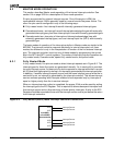
Six pins are provided for external interrupt sources. One of these pins is NMI, the
nonmaskable interrupt. NMI is generally used for unusual events like power failure. The
other five pins can be configured in any of the following ways:
n Fully nested mode—five interrupt lines with internally-generated interrupt types
n Cascade mode one—an interrupt line and interrupt acknowledge line pair with externally-
generated interrupt types, plus three interrupt input lines with internally-generated types
n Cascade mode two—two pairs of interrupt and interrupt acknowledge lines with
externally-generated interrupt types, and one interrupt input line (INT4) with internally-
generated type
The basic modes of operation of the interrupt controller in Master mode are similar to the
82C59A. The interrupt controller responds identically to internal interrupts in all three
modes, the difference is only in the interpretation of function of the five external interrupt
pins. The interrupt controller is set into one of these modes by programming the correct
bits in the INT0 and INT1 control registers. The modes of interrupt controller operation are
fully nested mode, Cascade mode, special fully nested mode, and polled mode.
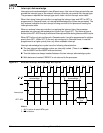
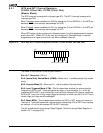
8.2.1 Fully Nested Mode
In fully nested mode, five pins are used as direct interrupt requests as in Figure 8-2. The
interrupt types for these five inputs are generated internally. An in-service bit is provided
for every interrupt source. If a lower-priority device requests an interrupt while the in-service
bit (IS) is set for a higher priority interrupt, no interrupt is generated by the interrupt controller.
In addition, if another interrupt request occurs from the same interrupt source while the in-
service bit is set, no interrupt is generated by the interrupt controller. This allows interrupt
service routines operating with interrupts enabled to be suspended only by interrupts of
equal or higher priority than the in-service interrupt.
When an interrupt service routine is completed, the proper IS bit must be reset by writing
the interrupt type to the EOI Register. This is required to allow subsequent interrupts from
this interrupt source and to allow servicing of lower-priority interrupts. A write to the EOI
Register should be executed at the end of the interrupt service routine just before the return
from interrupt instruction.
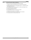
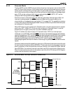
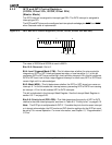
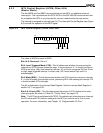
Figure 8-2 Fully Nested (Direct) Mode Interrupt Controller Connections
Am186ER
or Am188ER
Microcontroller
INT1
INT3
Interrupt Source
Interrupt Source
Interrupt Source
Interrupt Source
INT2
INT0
INT4
Interrupt Source